aircraft engine design

مهدي كياني

کاربر فعال مهندسی هوافضا
Dr. Hans von Ohain and Sir Frank Whittle are recognized as the co-inventors of the jet engine. Each was working separately and knew nothing of the others work. Although Whittle started first, von Ohain was first to design and develop a turbojet engine to power an aircraft.
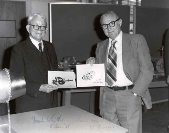
Of the many honors received by both, the most significant honor was probably "The Charles Draper Prize" in 1992 which was given to both Hans von Ohain and Sir Frank Whittle for their efforts and contributions to aviation and mankind. "The Charles Draper Prize" is recognized as the equivalent to the Nobel Prize in technology.

Hans von Ohain
Born Dessau, Germany December 14, 1911
Died Melbourne, Florida 13 March, 1998
Hans von Ohain started development of the turbojet engine in the early 1930's while in the midst of his doctorial studies at Goettinger University in Germany. By 1935 he had developed a test engine(shown below, left with master mechanic Max Hahn) to demonstrate his ideas. He asked Ernst Heinkel, an aircraft manufacturer for support rather than approach the the German engine industry (they probably would not have been interested). Heinkel (shown below, right with Von Ohain standing) saw the promise in von Ohain's invention - a means to build the fastest airplane in the world. At the end of February 1937, the He S-1 turbojet engine with hydrogen fuel was tested and produced a thrust of 250 pounds at 10,000 rpm. Von Ohain reported: "The apparatus fully met expectations. It reached the anticipated performance, it handled well in acceleration and deceleration, probably because of the relatively small moment of inertia of the compressor and turbine rotor and the great stability of the hydrogen combustion over the wide operational range."

Max Hahn with test engine.

Heinkel (seated) and von Ohain toasting.


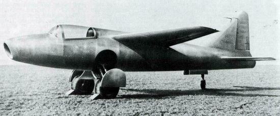
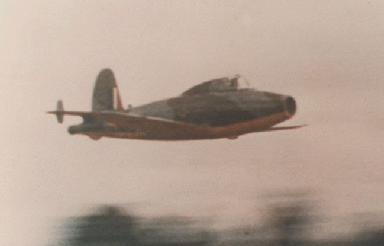
The He S-3 engine used to power the He-178 aircraft. So impressed with the engine tests, Heikel pressed for an accelerated flight engine program. Von Ohain's team began development on the He S-3 engine. One of the main technology hurdles they faced was the development of a liquid fuel combustor. This resulted in the engine shown to the left with a front combustor. Detailed design began in early 1938 on the test aircraft, the He-178 (shown below). In early 1939, both the engine and the airframe were completed, but the net thrust was below requirements. After several internal engine adjustments, the engine was ready. On August 27, 1939, Heinkel's test pilot, E. Warsitz, made the first successful flight of a jet power aircraft.

First jet aircraft, Heinkel He-178 powered by one He S-3 turbojet engine.

Hans von Ohain at age 25. Picture was taken in early 1937 after first run of hydrogen test engine.

Hans von Ohain in his 50's. Picture taken in 1960's.
Other Tributes to Hans von Ohain: 1 2 3


Sir Frank Whittle
Born Coventry, England June 1, 1907
Died Baltimore, MD August 9, 1996
Frank Whittle was a 22 year old Royal Air Force (RAF) officer when he first conceived of the use of a gas turbine engine to power an aircraft. In January of 1930, he filed for a patent which was granted in 1932 and published widely. However he received very little encouragement from the Air Ministry or industry. After receiving support from investment bankers, Powers Jets was established in 1936 and Whittle was assigned to the company on special military duty to work on the design and development of his jet engine.
The first real run of the first experimental engine (shown below) was in April of 1937. This engine has a centrifugal compressor and axial flow turbine. Whittle describes it as follows: "The experience was frightening. The starting procedure went as planned. By a system of hand signals from me the engine was accelerated to 2,000 rpm by the electric motor. I turned on a pilot fuel jet and ignited it with a hand turned magneto connected to a spark plug with extended electrodes; then I received a 'thumbs up' signal from a test fitter looking into the combustion chamber through a small quartz 'window.' When I started to open the fuel supply valve to the main burner (the fuel was diesel oil), immediately, with a rising scream, the engine began to accelerate out of control. I promptly shut the control valve, but the uncontrolled acceleration continued. Everyone around took to their heels except me. I was paralyzed with fright and remained rooted to the spot." The reason for the uncontrolled acceleration was that prior bleeding of fuel lines had created a pool of fuel in the combustor. "The ignition of this was the cause of the 'runaway.' A drain was quickly fitted to ensure that this could not happen again."

The original version of Whittle's first experimental engine first run in April of 1937.
During the next year, many development problems were solved and the experimental engine reconstructed several times. The resulting engine with ten combustion chambers (shown below, left) performed well enough to finally received support from the Air Ministry in 1939.

First experimental engine, after the second reconstruction in 1938.

Frank Whittle using a slide rule to perform calculations.

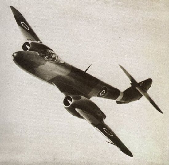
The W.1 turbojet engine used to power the Gloster E28/39 aircraft. It was designed to produce a static thrust of 1,240 lbs at 17,750 rpm. This engine was also the basis of the design of the General Electric I-14 turbojet engine used to power the Bell XP-59A twin engine experimental fighter. In June 1939, the Air Ministry was finally convinced of the merits of Whittle' invention. They then decided to have a flight engine built (the W.1) and have the Gloster Aircraft Company build an experimental airplane - the E28/39.
The aircraft was completed in March 1941 and the engine in May 1941. First flight of the E28/39 occured on the evening of May 15, 1941.
In recognition of his singular contributions, Frank Whittle was knighted by King George VI in 1948 and thus became Sir Frank Whittle.


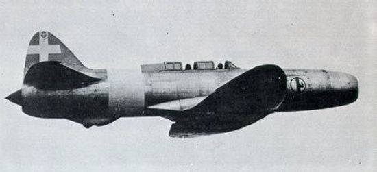
The Gloster E28/39 aircraft powered by one W.1 turbojet engine. Some Other Tributes to Sir Frank Whittle: 1 2 3 First Production Jet Aircraft
The Messerschmitt Me 262 jet fighter, first production jet aircraft, powered by two Jumo 004B turbojet engines. The Me 262 first flight was on July 18, 1942. The Jumo 004 was designed by Dr. Anselm Franz of the the Junkers Engine Company.

Drawing of Jumo 004B turbojet engine showing air cooling system [thrust = 2000 lb, airflow = 46.6 lb/sec, pressure ratio = 3.14, turbine inlet temperature = 1427F, fuel consumption = 1.4 (lb/hr)/lb-thrust, engine weight = 1650 lb, diameter = 30 in, length = 152 in, efficiencies: 78% compressor, 95% combustor, 79.5% turbine].

[FONT=verdana, arial, helvetica] [/FONT]


مهدي كياني

کاربر فعال مهندسی هوافضا
Pictures of Aircraft Gas Turbine Engines

Hosted by Jack Mattingly


List of images without preview


Preview of full images using thumb-nail images


  • Commercial High Bypass Turbofan Engines
  • Other Commercial Gas Turbine Engines
  • Military Afterburning Turbofan Engines
  • Other Military Gas Turbine Engines
 

مهدي كياني

کاربر فعال مهندسی هوافضا
اهل طراحی هستی بیا تو

اهل طراحی هستی بیا تو

سلام به بچه های با حال اهل طراحی
اگه حالشو داشتید بیان اینجا مقاله های باحال طراحی موتور و یا قسمت های دیگه رو جمع آوری کنیم
 

Sparrow

مدیر تالار مهندسی هوافضا
مدیر تالار
سلام به بچه های با حال اهل طراحی
اگه حالشو داشتید بیان اینجا مقاله های باحال طراحی موتور و یا قسمت های دیگه رو جمع آوری کنیم

ممنون از شما به خاطر پست ها و تاپیک های مفیدتون.
به نظر من اگر که کاتالوگ موتورها رو اینجا قرار بدیم خیلی مفید خواهد بود. هم به جهت طراحی و هم به جهت مطالعه. من سعی می کنم موتورهای P & W رو بذارم.
 

مهدي كياني

کاربر فعال مهندسی هوافضا
General Electric J47 Jet Engine

General Electric J47 Jet Engine


[FONT=Arial, Helvetica, sans-serif]General Electric J47 Jet Engine[/FONT]

[FONT=Arial, Helvetica, sans-serif]These B-47 planes use jet engines to provide thrust and to move them forward. Photo from the collection of Mark Natola.[/FONT] [FONT=Arial, Helvetica, sans-serif]..the first engine with axial flow approved for non-military use. Axial flow is airflow straight through a cylinder.[/FONT]


[FONT=Arial, Helvetica, sans-serif]Specs[/FONT][FONT=Arial, Helvetica, sans-serif]
First test flight: 1948
Engine weight: 1,100 kg (2,500 pounds)
Thrust: 22,000 newtons (5,000 pounds of force)
Maximum altitude: 15 km (50,000 feet)
[/FONT]
[FONT=Arial, Helvetica, sans-serif]History[/FONT][FONT=Arial, Helvetica, sans-serif]
The J47 engine was first conceived in March 1946. Since that time many variations of the J47, including many technical innovations, have been designed and produced. In all, GE built over 30,000 J47 engines. It has applications in many types of aircraft, including bombers, reconnaissance, interceptors, and fighter planes.
[/FONT]
[FONT=Arial, Helvetica, sans-serif]The J-47 turbojet displayed at the Science Center has an afterburner to increase engine power at takeoff and during altitude acceleration. It also has an anti-icing feature, a more efficient compressor for increased airflow, and a high-altitude starting system.[/FONT]

[FONT=Arial, Helvetica, sans-serif]Jet Engine Function
[/FONT][FONT=Arial, Helvetica, sans-serif]The main purpose of a jet engine is to shoot air quickly out through the back of the engine, which pushes the plane forward. Just like air rushing out of a balloon makes the balloon fly around, hot gas shooting out the back of an engine thrusts the plane ahead. Jet engines work like piston engines in that they have four steps - intake, compression, combustion and exhaust. The four steps take place in one continuous flow rather than in back and forth actions. Air is sucked in at the intake and is compressed by a compressor turbine or fan. This dense air is then mixed with fuel, which is burned, causing the gases to expand very quickly. The hot burning mixture increases speed rapidly and flows past a series of turbines, causing them to rotate at high speed. The turbines are mounted on the same shaft as the compressor, which provides its rotation. Then the exhaust gases are emitted past a cone, where Newton's Third Law of Motion takes over. On the diagram below, you can see the four steps air goes through as it passes through the jet engine. Definitions for each of the steps are included below the diagram.
[/FONT]


[FONT=Arial, Helvetica, sans-serif]Intake[/FONT] [FONT=Arial, Helvetica, sans-serif]sucks air into the engine.[/FONT] [FONT=Arial, Helvetica, sans-serif]Compression[/FONT] [FONT=Arial, Helvetica, sans-serif]squeezes the air. Row after row of spinning blades force air through and compress it, raising the air pressure. The wing-shaped blades get closer and closer together deeper into the engine.[/FONT] [FONT=Arial, Helvetica, sans-serif]Combustion[/FONT] [FONT=Arial, Helvetica, sans-serif]heats up the air. In the combustion chamber, pressurized air mixes with jet fuel. A flame heats the mix, and it expands very quickly.[/FONT] [FONT=Arial, Helvetica, sans-serif]Exhaust[/FONT] [FONT=Arial, Helvetica, sans-serif]shoots the heated air out the back of the engine. Fast-expanding hot gases from the combustion chamber shoot out the exhaust nozzle. Pushing the fast-expanding hot gases from the combustion chamber out the back moves the engine forward.[/FONT] [FONT=Arial, Helvetica, sans-serif]Jet engines provide great power with light weight, simplicity and reliability. However, they are expensive to build and use a lot more fuel than piston engines of similar power. They are more efficient than piston engines at high altitudes, where airplanes can fly faster in the thinner air. They may provide thrust in one of several ways: from their exhaust (pure jet), by driving a fan (fan jet), or a propeller (prop jet). To learn more about jet engines, check out the links below.[/FONT]
[FONT=Arial, Helvetica, sans-serif] J47 and Jet Engine Links
[/FONT][FONT=Arial, Helvetica, sans-serif]General Electric J47 Turbojet Engine
This page from the Air Force Museum's Engine Gallery shows a photo of a J47 engine, engine stats and even the engine cost.
[/FONT]
[FONT=Arial, Helvetica, sans-serif]How Gas Turbine Engines Work
How Stuff Works offers a great collection of pages explaining the workings of gas turbine engines, including jet engines. You'll also find a very helpful listing of advantages and disadvantages to turbine engines and links to related books.
[/FONT]
[FONT=Arial, Helvetica, sans-serif]Ultra-Efficient Engine Technology Kid's Page: Engines
NASA created this page on how jet engines work. The page features a list of the major parts of a jet engine along with definitions and illustrations, a history of jet engines, and information about many different types of jet engines. If you're interested, you can also follow links to plane-inspired online games.
[/FONT]
[FONT=Arial, Helvetica, sans-serif]Beginner's Guide to Propulsion
Despite the title, this page (designed for secondary school teachers as part of the Glenn Learning Technologies Project) features some detailed information about propulsion. The page includes links to definitions of important terms, and even an EngineSim that lets you design and test jet engines on your computer.
[/FONT]


مهدي كياني

کاربر فعال مهندسی هوافضا
Turbojet

Turbojet

Turbojet

From Wikipedia, the free encyclopedia

.
Turbojet


Part of a series on
Aircraft propulsion Shaft engines turning propellers, rotors, Ducted fans and propfans Reaction engines External combustion engines Rocket-powered aircraft Steam-powered aircraft Motorjet Internal combustion engines PulsejetPiston engine RamjetWankel engine Turbine engines Turbine enginesTurbojetTurboprop/turboshaftTurbofan Other
Human-powered aircraft
Electric aircraft

Turbojets are the oldest kind of general purpose jet engines. Two engineers, Frank Whittle in the United Kingdom and Hans von Ohain in Germany, developed the concept independently into practical engines during the late 1930s, although credit for the first turbojet is given to Whittle who submitted the first proposal and held a UK patent that was widely read.

Turbojets consist of an air inlet, an air compressor, a combustion chamber, a gas turbine (that drives the air compressor) and a nozzle. The air is compressed into the chamber, heated and expanded by the fuel combustion and then allowed to expand out through the turbine into the nozzle where it is accelerated to high speed to provide propulsion.[1]

Turbojets are quite inefficient (if flown below about Mach 2) and very noisy. Most modern aircraft use turbofans instead for economic reasons. Turbojets are still very common in medium range cruise missiles,[citation needed] due to their high exhaust speed, low frontal area and relative simplicity.
Contents


History


Albert Fonó's German patent for jet Engines (January 1928). The third illustration is a turbojet

The first patent for using a gas turbine to power an aircraft was filed in 1921 by Frenchman Maxime Guillaume.[2] His engine was to be an axial-flow turbojet, but was never constructed, as it would have required considerable advances over the state of the art in compressors.

Practical axial compressors were made possible by ideas from A.A.Griffith in a seminal paper in 1926 ("An Aerodynamic Theory of Turbine Design").


Heinkel He 178, the world's first aircraft to fly purely on turbojet power, using an HeS 3 engine

On 27 August 1939 the Heinkel He 178 became the world's first aircraft to fly under turbojet power, thus becoming the first practical jet plane. The first two operational turbojet aircraft, the Messerschmitt Me 262 and then the Gloster Meteor entered service towards the end of World War II in 1944.

A turbojet engine is used primarily to propel aircraft. Air is drawn into the rotating compressor via the intake and is compressed to a higher pressure before entering the combustion chamber. Fuel is mixed with the compressed air and ignited by a flame in the eddy of a flame holder. This combustion process significantly raises the temperature of the gas. Hot combustion products leaving the combustor expand through the turbine where power is extracted to drive the compressor. Although this expansion process reduces the turbine exit gas temperature and pressure, both parameters are usually still well above ambient conditions. The gas stream exiting the turbine expands to ambient pressure via the propelling nozzle, producing a high velocity jet in the exhaust plume. If the momentum of the exhaust stream exceeds the momentum of the intake stream, the impulse is positive, thus, there is a net forward thrust upon the airframe.

Early generation jet engines were pure turbojets, designed intially to use a centrifugal compressor (as in the Heinkel HeS 3), and very shortly afterwards began to use Axial compressors (as in the Junkers Jumo 004) for a smaller diameter to the overall engine housing. They were used because they were able to achieve very high altitudes and speeds, much higher than propeller engines, because of a better compression ratio and because of their high exhaust speed. However they were not very fuel efficient. Modern jet engines are mainly turbofans, where a proportion of the air entering the intake bypasses the combustor; this proportion depends on the engine's bypass ratio. This makes turbofans much more efficient than turbojets at high subsonic/transonic and low supersonic speeds.

One of the most recent uses of turbojet engines was the Olympus 593 on Concorde. Concorde used turbojet engines because it turns out that the small cross-section and high exhaust speed is ideal for operation at Mach 2. Concorde's engine burnt less fuel to produce a given thrust for a mile at Mach 2.0 than a modern high-bypass turbofan such as General Electric CF6 at its Mach 0.86 optimum speed. Concorde's airframe, however, was far less efficient than that of any subsonic airliner.

Although ramjet engines are simpler in design as they have virtually no moving parts, they are incapable of operating at low flight speeds.


Air intake


An animation of an axial compressor. The darker colored blades are the stators.

Schematic diagram showing the operation of a centrifugal flow turbojet engine. The compressor is driven via the turbine stage and throws the air outwards, requiring it to be redirected parallel to the axis of thrust.

Schematic diagram showing the operation of an axial flow turbojet engine. Here, the compressor is again driven by the turbine, but the air flow remains parallel to the axis of thrust.

Preceding the compressor is the air intake (or inlet). It is designed to be as efficient as possible at recovering the ram pressure of the air streamtube approaching the intake. The air leaving the intake then enters the compressor. The stators (stationary blades) guide the airflow of the compressed gases.


Compressor


The compressor is driven by the turbine. The compressor rotates at very high speed, adding energy to the airflow and at the same time squeezing (compressing) it into a smaller space. Compressing the air increases its pressure and temperature.

In most turbojet-powered aircraft, bleed air is extracted from the compressor section at various stages to perform a variety of jobs including air conditioning/pressurization, engine inlet anti-icing and turbine cooling. Bleeding air off decreases the overall efficiency of the engine, but the usefulness of the compressed air outweighs the loss in efficiency.

Several types of compressor are used in turbojets and gas turbines in general: axial, centrifugal, axial-centrifugal, double-centrifugal, etc.

Early turbojet compressors had overall pressure ratios as low as 5:1 (as do a lot of simple auxiliary power units and small propulsion turbojets today). Aerodynamic improvements, plus splitting the compression system into two separate units and/or incorporating variable compressor geometry, enabled later turbojets to have overall pressure ratios of 15:1 or more. For comparison, modern civil turbofan engines have overall pressure ratios of 44:1 or more.

After leaving the compressor section, the compressed air enters the combustion chamber.


s.​
 

مهدي كياني

کاربر فعال مهندسی هوافضا
Combustion chamber

The burning process in the combustor is significantly different from that in a piston engine. In a piston engine the burning gases are confined to a small volume and, as the fuel burns, the pressure increases dramatically. In a turbojet the air and fuel mixture passes unconfined through the combustion chamber. As the mixture burns its temperature increases dramatically, but the pressure actually decreases a few percent.​
The fuel-air mixture must be brought almost to a stop so that a stable flame can be maintained.
This occurs just after the start of the combustion chamber. The aft part of this flame front is allowed to progress rearward. This ensures that all of the fuel is burned, as the flame becomes hotter when it leans out, and because of the shape of the combustion chamber the flow is accelerated rearwards. Some pressure drop is required, as it is the reason why the expanding gases travel out the rear of the engine rather than out the front. Less than 25% of the air is involved in combustion, in some engines as little as 12%, the rest acting as a reservoir to absorb the heating effects of the burning fuel.​
Another difference between piston engines and jet engines is that the peak flame temperature in a piston engine is experienced only momentarily in a small portion of the full cycle. The combustor in a jet engine is exposed to the peak flame temperature continuously and operates at a pressure high enough that a stoichiometric fuel-air ratio would melt the can and everything downstream. Instead, jet engines run a very lean mixture, so lean that it would not normally support combustion. A central core of the flow (primary airflow) is mixed with enough fuel to burn readily. The cans are carefully shaped to maintain a layer of fresh unburned air between the metal surfaces and the central core. This unburned air (secondary airflow) mixes into the burned gases to bring the temperature down to something a turbine can tolerate.​
Turbine

Hot gases leaving the combustor are allowed to expand through the turbine. Turbines are usually made up of high temperature metals such as inconel to resist the high temperature, and frequently have built-in cooling channels.​
In the first stage the turbine is largely an impulse turbine (similar to a pelton wheel) and rotates because of the impact of the hot gas stream. Later stages are convergent ducts that accelerate the gas rearward and gain energy from that process. Pressure drops, and energy is transferred into the shaft. The turbine's rotational energy is used primarily to drive the compressor. Some shaft power is extracted to drive accessories, like fuel, oil, and hydraulic pumps. Because of its significantly higher entry temperature, the turbine pressure ratio is much lower than that of the compressor. In a turbojet almost two thirds of all the power generated by burning fuel is used by the compressor to compress the air for the engine.​
Nozzle

Main article: propelling nozzle
After the turbine, the gases are allowed to expand through the exhaust nozzle to atmospheric pressure, producing a high velocity jet in the exhaust plume. In a convergent nozzle, the ducting narrows progressively to a throat. The nozzle pressure ratio on a turbojet is usually high enough for the expanding gases to reach Mach 1.0 and choke the throat. Normally, the flow will go supersonic in the exhaust plume outside the engine.​
If, however, a convergent-divergent "de Laval" nozzle is fitted, the divergent (increasing flow area) section allows the gases to reach supersonic velocity within the nozzle itself. This is slightly more efficient on thrust than using a convergent nozzle. There is, however, the added weight and complexity since the con-di nozzle must be fully variable to cope basically with engine throttling.​
Net thrust

The net thrust
of a turbojet is given by:[3][4]
where:​
is the rate of flow of air through the engine
is the rate of flow of fuel entering the engine
is the speed of the jet (the exhaust plume) and is assumed to be less than sonic velocity
is the true airspeed of the aircraft
represents the nozzle gross thrust
represents the ram drag of the intake.​
If the speed of the jet is equal to sonic velocity the nozzle is said to be choked. If the nozzle is choked the pressure at the nozzle exit plane is greater than atmospheric pressure, and extra terms must be added to the above equation to account for the pressure thrust. [5]
The rate of flow of fuel entering the engine is very small compared with the rate of flow of air.[3] If the contribution of fuel to the nozzle gross thrust is ignored, the net thrust is:​
The speed of the jet
must exceed the true airspeed of the aircraft
if there is to be a net forward thrust on the airframe.​
Thrust to power ratio

A simple turbojet engine will produce thrust of approximately: 2.5 pounds force per horsepower (15 mN/W).​
Afterburner

An afterburner or "reheat jetpipe" is a device added to the rear of the jet engine. It provides a means of spraying fuel directly into the hot exhaust, where it ignites and boosts available thrust significantly; a drawback is its very high fuel consumption rate. Afterburners are used mostly on military aircraft, but the two supersonic civilian transports, Concorde and the TU-144, also utilized afterburners, as does Scaled Composites White Knight, a carrier aircraft for the experimental SpaceShipOne suborbital spacecraft.​
Thrust reverser

A thrust reverser is, essentially, a pair of clamshell doors mounted at the rear of the engine which, when deployed, divert thrust normal to the jet engine flow to help slow an aircraft upon landing. They are often used in conjunction with spoilers. The accidental deployment of a thrust reverser during flight is a dangerous event that can lead to loss of control and destruction of the aircraft. Thrust reversers are more convenient than drogue parachutes.​
 

مهدي كياني

کاربر فعال مهندسی هوافضا
Cycle improvements

Thermodynamics of a jet engine are modelled approximately by a Brayton Cycle.​
Increasing the overall pressure ratio of the compression system raises the combustor entry temperature. Therefore, at a fixed fuel flow and airflow, there is an increase in turbine inlet temperature. Although the higher temperature rise across the compression system, implies a larger temperature drop over the turbine system, the nozzle temperature is unaffected, because the same amount of heat is being added to the system. There is, however, a rise in nozzle pressure, because overall pressure ratio increases faster than the turbine expansion ratio. Consequently, net thrust increases, while specific fuel consumption (fuel flow/net thrust) decreases.​
Thus turbojets can be made more fuel efficient by raising overall pressure ratio and turbine inlet temperature in union. However, better turbine materials and/or improved vane/blade cooling are required to cope with increases in both turbine inlet temperature and compressor delivery temperature. Increasing the latter requires better compressor materials.​
By Increasing the useful work to system , by minimizing the heat losses by conduction etc and minimizing the inlet temperature ratio up to a certain level will increase the themal efficiency of the turbo jet engine.​
Early designs


J85-GE-17A turbojet engine from General Electric (1970)
Early German engines had serious problems controlling the turbine inlet temperature. A lack of suitable alloys due to war shortages meant the turbine rotor and stator blades would sometimes disintegrate on first operation and never lasted long. Their early engines averaged 10-25 hours of operation before failing—often with chunks of metal flying out the back of the engine when the turbine overheated. British engines tended to fare better, running for 150 hours between overhauls. A few of the original fighters still exist with their original engines, but many have been re-engined with more modern engines with greater fuel efficiency and a longer TBO (such as the reproduction Me-262 powered by General Electric J85s).​
The United States had the best materials because of their reliance on turbo/supercharging in high altitude bombers of World War II. For a time some US jet engines included the ability to inject water into the engine to cool the compressed flow before combustion, usually during takeoff. The water would tend to prevent complete combustion and as a result the engine ran cooler again, but the planes would take off leaving a huge plume of smoke.​
Today these problems are much better handled, but temperature still limits turbojet airspeeds in supersonic flight. At the very highest speeds, the compression of the intake air raises the temperatures throughout the engine to the point that the turbine blades would melt, forcing a reduction in fuel flow to lower temperatures, but giving a reduced thrust and thus limiting the top speed. Ramjets and scramjets do not have turbine blades; therefore they are able to fly faster, and rockets run even hotter still.​
At lower speeds, better materials have increased the critical temperature, and automatic fuel management controls have made it nearly impossible to overheat the engine.​
References


  1. ^ "Turbojet Engine". NASA Glenn Research Center. http://www.grc.nasa.gov/WWW/K-12/airplane/aturbj.html. Retrieved on 2009-05-06.
  2. ^ Maxime Guillaume,"Propulseur par réaction sur l'air," French patent FR patent 534801 (filed: 3 May 1921; issued: 13 January 1922)
  3. ^ a b Cumpsty, Nicholas (2003). "3.1". Jet Propulsion (2nd ed.). Cambridge University Press. ISBN 0-521-541441.
  4. ^ "Turbojet Thrust". NASA Glenn Research Center. http://www.grc.nasa.gov/WWW/K-12/airplane/turbth.html. Retrieved on 2009-05-06.
  5. ^ Cumpsty, Jet Propulsion, Section 6.3
Springer, Edwin H. (2001). Constructing A Turbocharger Turbojet Engine. Turbojet Technologie​
 

مهدي كياني

کاربر فعال مهندسی هوافضا
How Do Jet Engine's Work

How Do Jet Engine's Work

How Do Jet Engine's Work?


[SIZE=-1]A jet engine works on the principle of [/SIZE] [SIZE=-1] Sir Isaac Newton[/SIZE][SIZE=-1]'s third law of physics, i.e. for every action there is an equal and opposite re-action. The action of forcing gases out from the rear of the jet engine results in a re-active force in the opposite direction, and is commonly referred to as 'thrust'.[/SIZE] This thrust is measured in pounds force (lbf ), kilograms force (kgf ), or Newtons (N).[SIZE=-1] Engines of this type are often referred to as 'Reaction Engines', a rocket engine being another example. Newton's third law and the action of a jet can be demonstrated in simple terms by inflating a balloon and releasing it, the escaping air propels the balloon in the opposite direction. [/SIZE]

[SIZE=-1] Creating thrust takes energy. The energy required is obtained from burning fuels, whether it be in gas or liquid form such as propane, kerosine, diesel or even vegetable oils! This fuel is normally combined with pressurised air to increase the efficiency and power output for a given engine size. This fuel/air mixture is burned in some form of combustion chamber where the resulting hot gases expand creating an increase in pressure inside the combustion chamber. The expanding gases are then used to do useful work. One example of this process is what happens inside the cylinder of a car engine. Air and fuel are drawn into the cylinder by the downward movement of the piston, the piston then moves up and squeezes this mixture which is then ignited. The fuel burns creating a sudden sharp rise in pressure inside the cylinder. This pressure then forces the piston back down producing mechanical work. The piston then moves back up the cylinder to eject the burnt fuel ready for another cycle. This process is commonly referred to as the 'Suck, Squeeze, Bang, Blow' cycle! (SSBB). [/SIZE]


Comparison of the Operation of a Typical Jet Engine

and a Four Stroke Internal Combustion Engine


[SIZE=-1] [/SIZE][SIZE=-1] The way a basic Turbojet engine burns it's fuel is exactly the same as in car engine, but instead of burning the fuel in discrete packets, the jet engine continuously sucks, squeezes, bangs and blows all at the same time! Also, instead of using the expanding gases to push on a piston, they are released through the turbine blades which takes some of the energy to drive the compressor, the rest being released to the atmosphere which results in 'Newtons' thrust described above. In a basic turbo jet, the air enters the front intake (suck) and is compressed by the compressor (squeeze), then forced into combustion chambers where fuel is sprayed into them and the mixture is ignited (bang). The gases which form expand rapidly, and are exhausted through the rear of the combustion chambers and out through the nozzle (blow) providing the forward thrust. Just before the gases enter the engine nozzle, they pass through a fan-like set of turbine blades which rotates the engine shaft. This shaft, in turn, rotates the compressor, thereby bringing in a fresh supply of air through the intake. All of these processes are happening at the same time. Engine thrust may be increased by the addition of an afterburner section into which extra fuel is sprayed into the exhausting gases ( which contains surplus hot oxygen ) to give the added thrust.[/SIZE]

At this point you may be asking yourself, "what actually makes it work?". When we effectively create a continuous explosion in our combustion chambers, what's to stop that explosion exiting the wrong way out of the compressor as opposed to out of the turbine? What is the physical explanation involved that will drive our engine ( and for that matter ANY jet engine ) the right way? The short answer to this is turbine to compressor 'Mechanical advantage'. For a slightly longer answer, I shall endeavour to explain below what it is and how it's used in a jet engine.
Lets start with an experiment. Imagine we have a typical jet engine like the one in the diagram above, that isn't running. We inject a quantity of fuel in to the combustion chamber, ignite it and create a single explosion. If we haven't over egged the pudding and the engine is still in one piece, some of the gases from the explosion will have exited out of the compressor intake ( not what we want ), but most of the gases will have exited out of the exhaust. As a result we find that our single explosion has given us a small kick of forward thrust, but additionally and crucially, has given the engine's compressor/shaft/turbine assembly a small rotational 'kick' in the direction it would have in normal operation. If our intention was to design and build a one-shot 'pulse' jet then we have succeeded, the compressor/shaft/turbine assembly's rotational 'kick' being a bit redundant from a design point of view and actually detrimental from an efficiency point of view, but comes in handy later on as we shall see! ;o)
The reason the gases exit mostly out of the exhaust which is what we want for forward thrust and also gives us our small rotational 'kick', is exhaust turbine to intake compressor mechanical advantage. How it works is this: following our explosion, the gases try to go equally in opposite directions through the compressor and turbine wheels, and due to the specific orientation of their blades, also tries to rotate them in opposite directions. If the compressor and turbine wheels were exactly the same size and shape, then we would have the situation where the exhaust gases would exit from both ends equally, generating equal forces in opposite directions resulting in no net thrust. Also, because the rotational forces acting on the compressor and turbine wheels would be equal and opposite, and because they are both connected to the same shaft, the whole compressor/shaft/turbine assembly would remain stationary. But the compressor and turbine wheels are not the same. The turbine blades are generally at a 'steeper' angle than the compressor blades, i.e. their 'pitch' is greater, and the area through which the gases flow through the turbine is generally larger than the compressor. The result of this is that the whole assembly is 'unbalanced' in terms of resistance to the explosion. What this means is that the gases will pass through the turbine more easily giving us our resultant net thrust in one direction, but equally importantly, because of the steeper blade angles of the turbine, the exiting gases give the turbine wheel more torque or 'turning force' in one direction than the compressor wheel's turning force in the opposite direction. The net result of these unbalanced torque's or turning forces is that the whole compressor/shaft/turbine assembly is given a rotational 'kick' in the direction that favours the turbine. This is the turbine to compressor mechanical advantage mentioned earlier that is employed in jet engines and is key to making them work! ;o)
OK, so we made one explosion, got a short pulse of thrust and spun our compressor/shaft/turbine assembly a bit in the right direction. But hey, why not do this again, immediately following our first explosion with another explosion and then another, etc, in rapid succession, making the engine spin faster and faster? Well, we can do this but we have to wait a bit before we can create another explosion. Our first explosion used up the available oxygen in the combustion chamber and it needs to be refreshed. This is where our now free-wheeling/spinning ( as a result of our mechanical advantage ) compressor comes into play. As it spins, it pulls in fresh air from the outside and eventually replenishes the combustion chamber with a charge of fresh air/oxygen. We can now inject more fuel, create our second explosion and get a second 'kick' of thrust. If we time things right, we can get our second explosion to add to the already spinning compressor/shaft/turbine and make it spin faster than before. We can repeat this process, creating our explosions more frequently as the compressor spins faster and faster, recharging the combustion chamber ever more quickly. Additionally, because of the ever increasing in-rush of air from the compressor, we find there is less and less tendency for our explosions to exit out of the compressor because of the ever increasing pressure barrier coming from that direction. Note also that so far our jet engine is still working discretely, i.e. it is still operating on the SSBB cycle as used in a car engine. Eventually though, there will come a point when our compressor is spinning so fast that it recharges the combustion chamber almost instantaneously, the pressure barrier it creates as a result of the in-rush of air means that our explosions exit fully out through the turbine only, and finally, our explosions are now so close together that we have left the discrete SSBB cycle behind and are indistinguishable from the continuous roar of a typical jet engine! ;o)
Although it is possible in theory to start a jet engine with discrete explosions, it would not be a very practical way to do it but more importantly would more than likely be a very destructive process! Normally the compressor/shaft/turbine is spun up either electrically, or pneumatically to a speed that sees enough in-flow of air from the compressor to make a decent pressure barrier, at which point enough fuel is introduced and burned so that it can take over from the 'starter motor'. This is the point at which the engine can be said to be 'self-sustaining' or 'idling'.
A bit of a long winded explanation but I hope this helps to give a clearer understanding of how things work! ;o) A slightly different and more mathematical approach ( although still employing the mechanical advantage principle ) can be found here courtesy J.S.Denker
 

مهدي كياني

کاربر فعال مهندسی هوافضا
Using a Turbocharger for a Jet Engine


KKK-K26 Turbocharger


A turbocharger is used on internal combustion engines to increase the amount of air and consequently the amount of fuel that can be introduced into the engines cylinders and as a result increases the amount of power that can be produced for a given engine size.


Cross-Section Through a Typical Turbocharger


The turbocharger's compressor provides the pressurised air for the engines cylinders. The compressor wheel is driven by a turbine wheel via an interconnecting shaft. The turbine wheel is driven by the exhaust gases produced by the engine. The whole compressor/shaft/turbine rotating assembly is exactly the same setup as in a typical turbojet.


Flow Diagram for a T urbocharger in Normal Use


So, fortunately for us, a turbocharger already has two of the three major the elements that we need to build a turbojet, i.e. a compressor section and turbine section. The only difference between the turbocharger and a real commercial turbojet are the designs of the compressor and turbine wheels. In a commercial turbojet the wheels are designed to work 'axially' which means that the gases flow through the wheels along their axes of rotation.


Commercial Engine with Axial Wheels and Gas Flow

In a turbocharger, the wheels are designed to work 'radially' that is, the gases exit the compressor and enter the turbine in a radial direction, i.e. at right angles to their axis of rotation, which is the reason for the 'snail shell'-like shape to the housings. The reason for this is efficiency, radial compressors and turbines work more efficiently below a certain size, above this size axial compressors and turbines are used, but this is not an issue for us apart from one of design compactness.


Turbocharger with Radial Wheels and Gas Flow


The third element that we need to build our jet engine, requires us to build some form of suitable combustion chamber. A turbocharger, when bolted to an engine is almost behaving like a jet engine already, it provides compressed air to the engine's combustion chamber cylinder where fuel is burned, the resulting gases then being forced out of the chamber by the piston which spins the turbine wheel and hence driving the compressor. When we introduce a jet engine style combustion chamber we effectively replace the engine and it's cylinders for the burning of our fuel, turning the discrete 'suck, squeeze, bang, blow' cycle into a continuous one as in a real turbojet. The combustion chamber will essentially be a large can into which the fuel is sprayed and burned. The air from the turbocharger's compressor is fed in, fuel is added, burned and the resulting hot gases then exit the combustion chamber through a pipe connected to the inlet of the turbochargers turbine thereby completing the loop. Combustion chambers have been constructed using a variety of basic materials, built up from tubular steel or from modified fire extinguishers using mild or sometimes stainless steel for durability.
Because of the inherent design of the turbocharger ( radial inflow wheels as opposed to the more normal axial flow wheels ) and the fact that we are using it 'as is', the combustion chamber needs to be constructed 'outside' of the turbocharger as a separate unit. This leads to the construction of a jet engine that is bulkier, heavier and far less efficient, thrust for thrust, than their more streamlined commercial brethren ( both full-size and model jets ) but is the price we have to pay in order to reduce complexity and cost to achieve a real working jet.
 

مهدي كياني

کاربر فعال مهندسی هوافضا
Getting Started

Ok, so we know that we can use a turbocharger to build a jet engine, but how do we go about choosing the right turbo? What sort of thrust levels can we expect? How do I go about designing my combustion chamber? What other bits and pieces do we need to make it work such oil and fuel systems? Because of the numerous types of turbocharger out there and the varying levels of access to parts and materials that builders encounter, but moreover the fact that 'There Is More Than One Way To Do It..', there is no one definitive set of plans to go by. Instead, what is presented below are links to a set of guidelines ( 'Rules of Thumb' ) in Adobe Acrobat Reader format (.pdf) that have been an invaluable aid to myself and others to help get to grips with these problems and come up with working solutions. They were originally drawn up by Australian John Wallis a veteran DIY gas turbine builder and long time member of the DIYGasturbines Yahoo group. The 'Rules of Thumb' are reproduced here with his permission. You can see examples of John's (Racketmotorman) projects on the DIYGasturbines group and on Nick Haddocks website ( see Links below ).
The diagram below shows a typical layout of a DIY gas turbine and gives the names of the various parts ( click on diagram for a more detailed version ).


Naming Conventions


Abbreviations - Refer to these if you are unsure of certain terms Rule of Thumb N.o. 1 - Choosing a Turbo Rule of Thumb N.o. 2 - Oil Requirements Rule of Thumb N.o. 3 - Combustion Chambers Rule of Thumb N.o. 4 - Fuel Requirements Rule of Thumb N.o. 5 - Ignition Rule of Thumb N.o. 6 - Starters Rule of Thumb N.o. 7 - Jet Pipes and Nozzles Rule of Thumb N.o. 8 - Compressor Flows Rule of Thumb N.o. 9 - Thrust Rule of Thumb N.o. 10 - Fuel Consumption Rule of Thumb N.o. 11 - Freepower Turbines Rule of Thumb N.o. 12 - Afterburners Rule of Thumb N.o. 13 - Evaporators

Adobe Acrobat Reader for your particular operating system can be downloaded here.


مهدي كياني

کاربر فعال مهندسی هوافضا
Jet Engine Types

Jet Engine Types

[FONT=arial,helvetica] Jet Engine Types [/FONT]
[FONT=arial,helvetica] [/FONT]

  • [FONT=arial,helvetica] Can you explain how various jet engines work, including the turbojet, turbofan, turboprop, and turboshaft? In particular, what is the difference between a turbojet and a turbofan and which is more efficient?
    - question from Tieo Jing Jin [/FONT]
[FONT=arial,helvetica]The term "jet engine" is often used as a generic name for a variety of engines, including the turbojet, turbofan, turboprop, and ramjet. These engines all operate by the same basic principles, but each has its own distinct advantages and disadvantages. All jet engines operate by forcing incoming air into a tube where the air is compressed, mixed with fuel, burned, and exhausted at high speed to generate thrust. [/FONT] [FONT=arial,helvetica]The key to making a jet engine work is the compression of the incoming air. If uncompressed, the air-fuel mixture won't burn and the engine can't generate any thrust. Most members of the jet family employ a section of compressors, consisting of rotating blades, that slow the incoming air to create a high pressure. This compressed air is then forced into a combustion section where it is mixed with fuel and burned. As the high-pressure gases are exhausted, they are passed through a turbine section consisting of more rotating blades. In this region, the exhausting gases turn the turbine blades which are connected by a shaft to the compressor blades at the front of the engine. Thus, the exhaust turns the turbines which turn the compressors to bring in more air and keep the engine going. The combustion gases then continue to expand out through the nozzle creating a forward thrust. The above explanation describes a simple turbojet, as illustrated below. [/FONT]

[FONT=arial,helvetica]

Diagram of an axial-flow turbojet [/FONT] [FONT=arial,helvetica]The turbojet (and the turbofan) can also be fitted with an afterburner. An afterburner is simply a long tube placed in between the turbine and the nozzle in which additional fuel is added and burned to provide a significant boost in thrust. However, afterburners greatly increase fuel consumption, so aircraft can only use them for brief periods. [/FONT]

[FONT=arial,helvetica]

Comparison of a turbojet and a turbojet with an afterburner [/FONT] [FONT=arial,helvetica]A further variation on the turbojet is the turbofan. Although most components remain the same, the turbofan introduces a fan section in front of the compressors. The fan, another rotating series of blades, is also driven by the turbine, but its primary purpose is to force a large volume of air through outer ducts that go around the engine core. Although this "bypassed" air flow travels at much lower speeds, the large mass of air that is accelerated by the fan produces a significant thrust (in addition to that created by the turbojet core) without burning any additional fuel. Thus, the turbofan is much more fuel efficient than the turbojet. In addition, the low-speed air helps to cushion the noise of the jet core making the engine much quieter. [/FONT]

[FONT=arial,helvetica]

Comparison of a low-bypass turbofan with long ducts and a high-bypass turbofan with short ducts [/FONT] [FONT=arial,helvetica]Turbofans are typically broken into one of two categories--low-bypass ratio and high-bypass ratio--as illustrated above. The bypass ratio refers to the ratio of incoming air that passes through the fan ducts compared to the incoming air passing through the jet core. In a low-bypass turbofan, only a small amount of air passes through the fan ducts and the fan is of very small diameter. The fan in a high-bypass turbofan is much larger to force a large volume of air through the ducts. The low-bypass turbofan is more compact, but the high-bypass turbofan can produce much greater thrust, is more fuel efficient, and is much quieter. [/FONT]
[FONT=arial,helvetica]A concept similar to the turbofan is the turboprop. However, instead of the turbine driving a ducted fan, it drives a completely external propeller. Turboprops are commonly used on commuter aircraft and long-range planes that require great endurance like the P-3 Orion and Tu-95. [/FONT]

[FONT=arial,helvetica]

Schematic of a turboprop engine [/FONT] [FONT=arial,helvetica]The turboprop is attractive in these applications because of its high fuel efficiency, even greater than the turbofan. However, the noise and vibration produced by the propeller is a significant drawback, and the turboprop is limited to subsonic flight only. In a typical turboprop, the jet core produces about 15% of the thrust while the propeller generates the remaining 85%. [/FONT]
[FONT=arial,helvetica]Another noteworthy variation on the turbojet is the ramjet. The idea behind this type of engine is to remove all the rotary components of the engine (i.e. fans, compressors, and turbines) and allow the motion of the engine itself to compress incoming air for combustion. [/FONT]

[FONT=arial,helvetica]

Simple schematic of a ramjet [/FONT] [FONT=arial,helvetica]However, the price of this simplicity is that the ramjet can only produce thrust when it is already in motion. Instead of using a compressor to draw in air and compress it for combustion, the ramjet relies on the motion of the aircraft to ram air into the engine at high enough speed that it is already sufficiently compressed for combustion to occur. Since ramjets typically cannot function until reaching about 300 mph (485 km/h) at sea level, they have been rarely used on manned aircraft. However, the ramjet is more fuel efficient than turbojets or turbofans starting at about Mach 3 making them very attractive for use on missiles. Such missiles are typically launched using rocket motors that accelerate the vehicle to high-subsonic or low-supersonic speeds where the ramjet is engaged. [/FONT]
[FONT=arial,helvetica]Finally, let us talk briefly about the turboshaft, a version of the jet engine that powers nearly every helicopter built today. As the below image illustrates, the turboshaft utilizes many of the same components as a turbojet. [/FONT]

[FONT=arial,helvetica]

Schematic of a turboshaft engine [/FONT] [FONT=arial,helvetica]Air is drawn in through an inlet, compressed by low- and high-pressure compressor blades, mixed with fuel and burned in a combustion chamber, passed through turbine blades, and exhausted through a nozzle. The key difference between the turboshaft and previously discussed engines is that the turbine not only drives the compressors, but the shaft is also connected to a gear box that drives a helicopter's rotor blades. Although the engine shaft rotates about the horizontal, the gear box contains a sequence of gears that transform that motion to a rotation about the vertical axis as required by a helicopter main rotor. Helicopters also typically operate at much lower altitudes than aircraft where dust, sand, and other debris can easily be sucked into the engine. To address this problem, most turboshaft engines are equipped with a particle separator that filters out and expels the unwanted dust before the air flow reaches the compressor. [/FONT]

[FONT=arial,helvetica]

Schematic of a turboshaft engine particle separator [/FONT] [FONT=arial,helvetica]While the turboprop is still popular on aircraft where low fuel consumption is vital, nearly all aircraft today employ some version of the turbofan, usually high-bypass turbofans. The high thrust, low fuel consumption, and low noise levels of these engines make them well-suited to both military and commercial applications. Today, about the only use for turbojets and ramjets is in missiles. Air-breathing, long-range, subsonic missiles like the Tomahawk use turbojets since these are small, relatively low-cost systems that provide much greater range than is possible with a rocket of comparable size. Ramjets find applications on air-breathing, long-range, supersonic missiles for similar reasons. Turboshafts, of course, have displaced the piston engine as the primary powerplant used on helicopters. To continue learning more about aircraft propulsion, be sure to check out NASA's Learning Guide on Propulsion for a wealth of information, animations, and interactive applets about rockets, propellers, ramjets, and gas turbine engines.
- answer by Joe Yoon, 1 July 2001 [/FONT]
 

مهدي كياني

کاربر فعال مهندسی هوافضا
Jet Engine Development

Jet Engine Development

[FONT=arial,helvetica] Jet Engine Development [/FONT]


[FONT=arial,helvetica] [/FONT]

  • [FONT=arial,helvetica] Can you tell me who built and flew the first jet?
    - question from Jeff [/FONT] [FONT=arial,helvetica] I have some doubts about the first jet aircraft to fly, I believe I have read that an Italian jet aircraft flew in 1938-39. Could you find any information to confirm this?
    - question from Donald Shaw [/FONT]
[FONT=arial,helvetica]Two people are credited with inventing the jet engine. Sir Frank Whittle of Great Britain and Hans von Ohain of Germany both conceived of and built the first jet engines during the 1930s independently of each other. Whittle first originated the idea of the jet engine as a 22 year old officer in the Royal Air Force. He was awarded a patent for his innovation in 1932 and published his findings widely, but his ideas received little attention. Undeterred, Whittle went to work for a research company called Power Jets in 1936 and proceeded to develop a working model of his engine for possible military applications. After tackling and solving many technical problems, Whittle finally began receiving support from the British government in 1939. [/FONT]

[FONT=arial,helvetica]

Sir Frank Whittle and Hans von Ohain [/FONT]
[FONT=arial,helvetica]Meanwhile, German engineer Hans von Ohain had begun his own independent studies of jet propulsion in the early 1930s while working on his doctorate at Göttingen University. von Ohain had completed a working model of his engine by 1935 and approached Ernst Heinkel about building an aircraft to test such a device. Detailed work to design and build both a more powerful engine and a suitable airframe began in 1937, and von Ohain's engine was the first jet to fly when the Heinkel He 178 took to the air on 27 August 1939. [/FONT]

[FONT=arial,helvetica]

Heinkel He 178, the world's first jet-powered aircraft [/FONT]
[FONT=arial,helvetica]Back in Britain, the Air Ministry had become sufficiently impressed with Whittle's ground tests that an order was placed for a flight-worthy engine to be installed in an aircraft built by Gloster. The aircraft was completed in March 1941 and the engine the following May. Whittle's engine was first flown in the Gloster E.28/39 on 15 May 1941. [/FONT]

[FONT=arial,helvetica]

Gloster E.28/39 [/FONT]
[FONT=arial,helvetica]Although it took several more years for both nations to recognize the value of the jet engine, both the Royal Air Force and German Luftwaffe put out requests for jet-powered fighters. The resulting Messerschmitt Me 262 and Gloster Meteor both saw action in the closing months of World War II. [/FONT]

[FONT=arial,helvetica]

Messerschmitt Me 262 [/FONT]

[FONT=arial,helvetica]

Gloster Meteor [/FONT]
[FONT=arial,helvetica]Whittle's engine design was also provided to the United States where General Electric made some improvements and used the new engine in the Bell P-59 Airacomet. Other early jets developed during WWII included the Heinkel He 162 and He 280 as well as the Lockheed P-80 Shooting Star. Germany also supplied plans and even a complete jet engine to Japan late in the war allowing the Japanese to build their own version of the Me 262 known as the Kikka. [/FONT]
[FONT=arial,helvetica]Italy's entry into the "jet" arena was the Campini-Caproni CC-2. But unlike the German and British aircraft, the CC-2 was not powered by a true jet engine. To be more precise, the type of engine most people refer to as a jet is known by the more official title of a gas turbine. The most important component of the gas turbine is a stage towards the aft end of the engine called a turbine. Hot exhaust gases created by burning a mixture of fuel and incoming air passes through the turbine causing it to spin. This spinning motion provides power that is used to turn a shaft connected to a compressor stage at the forward end of the engine. The compressor pulls additional air into the engine and compresses it to a high pressure so that it can be combusted with fuel to continually produce thrust. This process is illustrated in the following diagram of the Junkers Jumo 004B turbojet engine used aboard the Me 262. [/FONT]

[FONT=arial,helvetica]

Me 262 turbojet engine schematic [/FONT]
[FONT=arial,helvetica]The engine used aboard the CC-2, on the other hand, operated in a fundamentally different manner. The concept was developed by Secondo Campini, an Italian engineer who began studying propulsion systems in the early 1930s. The idea he came up with was known as the thermojet, and it can be thought of as a hybrid between a classic piston-powered propeller engine and the turbojet. At the heart of the thermojet is a traditional internal combustion piston engine, like those that had been used since the days of the Wright brothers. A piston engine operates just like an engine in a typical automobile. A mixture of air and fuel is combusted inside a cylinder, and the force generated by that combustion is used to move a piston and generate mechanical work. In the case of an aircraft, that mechanical work turns a propeller in order to generate thrust. [/FONT]

[FONT=arial,helvetica]

CC-2 thermojet engine schematic [/FONT]
[FONT=arial,helvetica]What Campini did in his thermojet was place a piston engine within an enclosed duct, as illustrated above. The mechanical energy of this engine was used to turn three propellers placed behind the engine. Two of these ducted propellers were used to compress the incoming air while the third helped to direct the flow and minimize turbulence within the engine. This compressed air was mixed with fuel by means of a ring of kerosene injectors in the aft portion of the duct. The mixture was then combusted and exhausted out of the nozzle at high speed to produce thrust. Conceptually, the engine can almost be thought of as adding an afterburner to a piston-powered propeller engine. [/FONT]

[FONT=arial,helvetica]

Campini-Caproni CC-2 [/FONT]
[FONT=arial,helvetica]Though Campini's engine was an interesting innovation, it was not as efficient or effective as the turbojet. The thermojet was most efficient at sea level where the air density and pressure is highest, but generates increasingly less power as altitude increases. In addition, the thermojet was far larger and heavier than a turbojet, and the piston engine needed to power the compressors was quite complicated. Combined with the low efficiency of the burner stage, the maximum power output of the engine was quite low. For these reasons, the turbojet and the related turbofan have become the dominant forms of aviation propulsion while the thermojet faded into obscurity. One of the few applications where the thermojet found a home was in later versions of the Japanese Ohka kamikaze aircraft, but this engine was deemed too underpowered and replaced by a turbojet. [/FONT]
[FONT=arial,helvetica]As for what jet-powered plane flew first, the CC-2 was beaten out by Germany's He 178 by exactly one year. The He 178 first flew on 27 August 1939 and the Campini-Caproni CC-2 on 27 August 1940. Following closely behind was the British Gloster E.28/39 that took to the air for the first time on 15 May 1941.
- answer by Jeff Scott, 5 October 2003 [/FONT]


مهدي كياني

کاربر فعال مهندسی هوافضا
Jets and Rockets

Jets and Rockets

[FONT=arial,helvetica] Jets and Rockets [/FONT]


[FONT=arial,helvetica] [/FONT]

  • [FONT=arial,helvetica] What is the difference between a jet engine and a rocket engine?
    - question from name withheld [/FONT]
[FONT=arial,helvetica]In order to understand how an engine works, we first need to understand the process of combustion. Combustion is defined as the burning, or oxidation, of matter to produce energy. Two substances are necessary for combustion to occur--a fuel and an oxidizer. A fuel can be anything from the wood, coal, or natural gas used to produce heat in a furnace to gasoline or hydrogen used in an internal combustion engine. An oxidizer, as its name implies, is a substance that contains oxygen. [/FONT]

[FONT=arial,helvetica]

Simple representation of the combustion process [/FONT]
[FONT=arial,helvetica]The purpose of both the jet engine and the rocket engine is to combust a mixture of fuel and oxidizer. This combustion process generates a high-pressure exhaust that creates thrust to push a vehicle forward. The fundamental difference between the two types of engines, however, is where the oxidizer comes from. [/FONT]
[FONT=arial,helvetica]A jet engine obtains its oxidizer from the external atmosphere, as illustrated in the diagram below. Air enters the engine through an inlet and is then slowed down and compressed by a series of compressor blades. The compressed air is then mixed with fuel, typically a petroleum-based liquid similar to kerosene, and burned. The high-pressure gas is exhausted through a nozzle to generate thrust. [/FONT]

[FONT=arial,helvetica]

Schematic of a simple jet engine [/FONT]
[FONT=arial,helvetica]A rocket engine differs from a jet engine primarily in one key way. Whereas the jet pulls in oxidizer from the atmosphere, a rocket carries its own supply of oxygen aboard the vehicle. An example shown below is the liquid rocket engine. This class of rocket carries a liquid fuel and a liquid oxidizer in two separate tanks. The two liquids are pumped into a combustion chamber at some rate, called the mass flow rate, where they are mixed and burned. Just as in the jet engine described earlier, this combustion process generates a high-pressure gas that is exhausted through a nozzle to generate thrust. [/FONT]

[FONT=arial,helvetica]

Schematic of a liquid rocket engine [/FONT]
[FONT=arial,helvetica]There are many different combinations of liquids that can be combusted in liquid rockets. One of the more common combinations, however, is liquid hydrogen as the fuel and liquid oxygen as the oxidizer. Other common fuels include kerosene and hydrazine while a frequently used oxidizer is nitrogen tetroxide. Liquid rockets are most commonly used on large vehicles that launch payloads into space, like the American Delta and Titan, Russian Soyuz and Proton, and European Ariane rockets. [/FONT]
[FONT=arial,helvetica]Another major form of the rocket is the solid rocket motor, like that illustrated below. A solid rocket also carries both the fuel and oxidizer aboard the vehicle. The difference between a solid rocket and a liquid rocket, however, is that the fuel and oxidizer are mixed together and cast into a solid mass. This mixture is inert and does not burn under normal conditions. When exposed to a heat source, like an igniter, however, a flame travels along the surface of the solid and combusts the mixed fuel and oxidizer. Once started, this reaction cannot be stopped, and the flame front will continue combusting the solid fuel until none remains. [/FONT]

[FONT=arial,helvetica]

Schematic of a solid rocket motor [/FONT]
[FONT=arial,helvetica]Because they are so much easier to handle and store for long periods of time, solid rockets are commonly used on military missiles like Minuteman, AMRAAM, and HARM. The rocket motors that you and I can purchase in a store and use to launch model rockets are also solid rockets. [/FONT]
[FONT=arial,helvetica]However, while solid rockets are typically safer, they are usually not as powerful or efficient as their liquid cousins. Another advantage of liquid rockets is that they can also be throttled by slowing or increasing the rate at which fuel is combusted. A solid rocket, by comparison, cannot be stopped once ignited. For these reasons, a number of hybrid classes of rockets have been developed to take advantage of the strengths of each type. [/FONT]
[FONT=arial,helvetica]The aptly named hybrid rocket is a cross between a solid rocket and a liquid rocket. This type of rocket combusts a solid fuel using a liquid or gaseous oxidizer stored in a tank aboard the vehicle. The chief advantage of the hybrid rocket is the relative safety of the solid rocket, but the rocket can be throttled by adjusting the flow rate of the oxidizer. [/FONT]
[FONT=arial,helvetica]A similar device is the ducted rocket, which is a cross between a jet engine a solid rocket. The ducted rocket works in the same way as the hybrid rocket except that the oxygen is taken from the external atmosphere, like a jet, instead of carried aboard the vehicle. Calling such a device a "rocket" is a little confusing since we have already said that a rocket carries its own supply of oxidizer, but that is the name this class of propulsion system has been given. The ducted rocket is attractive as a potential booster for high-speed military missiles, but few such designs have entered service so far. [/FONT]
[FONT=arial,helvetica]To summarize, the primary difference between a jet and a rocket is that a rocket carries its own supply of oxygen internally while a jet must obtain oxygen from the external atmosphere. Another more technical way to explain this difference is that the fluid a jet engine accelerates to produce thrust is air from the atmosphere whereas the fluid a rocket accelerates to produce thrust is the exhaust from its own combustion process. It is for this reason that a rocket works in the vacuum of space, where there is no atmosphere, while a jet engine will not.
- answer by Jeff Scott, 1 February 2004 [/FONT]​
 

مهدي كياني

کاربر فعال مهندسی هوافضا
Turboprops and Jet Engines

Turboprops and Jet Engines

[FONT=arial,helvetica] Turboprops and Jet Engines [/FONT]


[FONT=arial,helvetica] [/FONT]

  • [FONT=arial,helvetica] I saw a comment on your site saying that the C-130 is powered by jet engines. Correct me if I am wrong, but I flew on a lot of C-130s and none had jet powered engines, they all had propellers.
    - question from Tim [/FONT]
[FONT=arial,helvetica]I understand your confusion. However, the C-130 actually is powered by jet engines. They are a class of jet engines called turboprops in which a small jet engine is used to turn a large propeller. You can learn more about how these engines work in another question we answered about the different kinds of jet engines. [/FONT]
[FONT=arial,helvetica]It is a common misconception that if a plane has propellers, then it cannot be a "jet." However, this is not so. The turboprops used on planes like the C-130, P-3 Orion, and many commuter planes such as the ATR-42 do indeed use propellers to generate thrust, but the basic technology that turns those propellers is based on the turbojet. In more general terms, a turbojet is a gas turbine engine, and that same gas turbine cycle is used to power a turboprop as well as a turbofan. A turbofan is just like a turboprop except that some of the power generated by the gas turbine core is used to turn a series of ducted fan blades that generate additional thrust. [/FONT]

[FONT=arial,helvetica]

Fundamental gas turbine core used in a turbojet, turboprop, and turbofan [/FONT]
[FONT=arial,helvetica]A similar class of engines that is just starting to be used on production aircraft is the propfan. Although the propfan also utilizes a gas turbine core, the power generated by the core is used to turn a series of unducted fan blades rather than propellers. These fan blades convert the power generated by the engine into thrust to push the aircraft forward. [/FONT]
[FONT=arial,helvetica]The key point to remember is that both the turboprop and the propfan are classified as "jets" since a jet engine is at the heart of the system. This is not true in the case of other propeller-driven aircraft, such as those of WWII or most modern-day light general aviation planes. These craft are powered by piston engines, a much different technology that is more akin to how an automobile engine works.
- answer by Joe Yoon, 3 August 2003 [/FONT]
[FONT=arial,helvetica]UPDATE! [/FONT]
[FONT=arial,helvetica]To further illustrate the point about turboprop engines being jet-powered, I recently came across the following quote in a copy of Skywest Airlines Magazine. The article was about the EMBRAER EMB-120 Brasilia commuter plane operated by the airline, and included the remark [/FONT]
[FONT=arial,helvetica] "...Don't be fooled by the propellers you see: the same technology that powers jet aircraft actually powers the EMB-120 as well. Like jet engines, the EMB-120 is powered by a gas turbine design, allowing for the superior reliability and power that jet engines enjoy..." [/FONT]​
[FONT=arial,helvetica]While the article does not mention the turboprop by name, it does a good job of summarizing the key points of our answer about the gas turbine core used in turbojet and turboprop engines. [/FONT]
[FONT=arial,helvetica] - answer by Jeff Scott, 19 September 2004 [/FONT]​
 

مهدي كياني

کاربر فعال مهندسی هوافضا
Turboshaft and Turboprop

Turboshaft and Turboprop

[FONT=arial,helvetica] Turboshaft and Turboprop [/FONT]


[FONT=arial,helvetica] [/FONT]

  • [FONT=arial,helvetica] I read on your site that a turboshaft uses a series of gear connections to turn a rotor blade. A lot of turboprop engines don't have a direct connection to the propeller but a connecion via a series of gears like a turboshaft. Would it be more appropriate to call these turboprops "turboshafts" then?
    - question from name withheld [/FONT]
[FONT=arial,helvetica]This question makes reference to two past articles discussing the types of jet engines and the turboprop. We have seen that both the turboprop and the turboshaft are types of jet engines because they use the gas turbine cycle. A gas turbine engine works by combusting a mixture of air and fuel to generate a high-speed exhaust. As this exhaust escapes, it passes through a series of blades called a turbine causing the blades to rotate. This rotation converts the thermal energy of the exhaust gases into mechanical energy. [/FONT]

[FONT=arial,helvetica]

Schematic of a turboshaft engine [/FONT]
[FONT=arial,helvetica]The turboshaft engine receives its name from the fact that this rotation is used to turn a shaft of some kind. In the aerospace field, the turboshaft engine is used on helicopters. The rotating shaft of the engine is used to turn the rotor blades that provide lift and forward motion of the vehicle. However, this application is only one of many to which the turboshaft has been applied. The power industry also makes use of turboshaft engines to generate electricity. In this case, the rotating shaft is used to rotate a coil through a magnetic field to generate electrical current. Turboshafts are also used in ships and boats where the rotating shaft turns the vehicle's propeller. Turboshafts can even be used on ground vehicles, particularly military tanks and some racecars. [/FONT]

[FONT=arial,helvetica]

Schematic of an electrical generator [/FONT]
[FONT=arial,helvetica]You are correct that there is a strong relationship between the turboshaft and another type of jet engine called the turboprop. The turboprop also uses a gas turbine core to turn a shaft. However, the turboprop gets its name from the fact that the shaft is connected to an aircraft propeller causing it to turn. Nevertheless, you are incorrect in saying that a turboprop must have a direct connection to the propeller. Perhaps your confusion is based on the following example provided in one of our previous explanations about this subject. This particular design does indeed illustrate a propeller that is directly connected to the engine shaft. [/FONT]

[FONT=arial,helvetica]

Schematic of a turboprop engine [/FONT]
[FONT=arial,helvetica]However, most turboprops, like that below, are not directly connected. The engine shaft is instead attached to a gearbox that is connected to the propeller. This system includes reduction gears that allow the engine shaft and propeller to spin at different rates. [/FONT]

[FONT=arial,helvetica]

Schematic of a turboprop engine with a gearbox [/FONT]
[FONT=arial,helvetica]It would be incorrect to call these engines turboshafts just because of how the engine shaft and propeller are connected. Any jet engine that turns a propeller is called a turboprop for that reason. However, it is correct to say that the turboprop is a subcategory or variant of the more generic class of engines known as turboshafts. In fact, a turboshaft is defined as any type of gas turbine engine that turns a shaft connected to something other than an aircraft propeller. [/FONT]
[FONT=arial,helvetica]Additional information on how a turboprop engine works, including several animated images, can be found at NASA's Learning Guide on Propulsion.
- answer by Greg Alexander, 2 January 2005 [/FONT]​
 

مهدي كياني

کاربر فعال مهندسی هوافضا
Propfan Engines

Propfan Engines

[FONT=arial,helvetica] Propfan Engines [/FONT]


[FONT=arial,helvetica] [/FONT]

  • [FONT=arial,helvetica] I once saw a plane that had a jet on one side but it also had a prop on the other. They were doing some kind of test. I've been trying to find out what kind of plane it is and I was hoping you guys would help me.
    - question from J. Rafols [/FONT]
[FONT=arial,helvetica]Since this information is so vague, it's hard to determine exactly what you saw, especially without a photo. I though at first that you might be talking about some kind of turboprop since a turboprop is a type of jet engine that has a propeller. The turboprop uses the same core engine as a turbojet, but the exhaust gases are used to turn a turbine that is connected to a gearbox that turns a large propeller. As the propeller turns, it accelerates air to produce thrust. Turboprops are very fuel efficient but limited to flight below the speed of sound. Common applications for turboprop engines include commuter aircraft like the ATR 42, cargo transports such as the C-130 Hercules, long-range surveillance platforms like the P-3 Orion, and early jetliners including the Tu-114, itself based on the Tu-95 bomber. [/FONT]
[FONT=arial,helvetica]However, I suspect that you may have seen something more unusual since it sounds like the engines on each side of the plane were different. Perhaps what you might have seen was an experimental propfan aircraft. A propfan is similar to a turbofan, or turboprop, in that it is powered by a jet engine core. Like the turbofan, the small jet core rotates at least one set of fan blades (often two or three), and these fans produce the majority of the thrust. However, the fans on a turbofan engine are contained within the engine nacelle ducting while those on a propfan are external like the propeller of a turboprop. It is for this reason that propfans are sometimes called unducted fans. Examples of propfan engines are shown below. [/FONT]

[FONT=arial,helvetica]

Experimental propfan engines being tested by NASA and Antonov [/FONT]
[FONT=arial,helvetica]Perhaps one of the most significant series of propfan studies was conducted during the late 1970s and early 1980s. This effort culminated in flight tests of the McDonnell Douglas MD-UHB Demo aircraft based on the MD-81 airframe. The MD-UHB was used to evaluate advanced, experimental propulsion technologies designed to offer airlines significant improvements in fuel efficiency and lower operational costs. [/FONT]

[FONT=arial,helvetica]

McDonnell Douglas MD-UHB unducted fan testbed [/FONT]
[FONT=arial,helvetica]The primary purpose of the technology demonstrator was to test the Pratt & Whitney-Allison 578-DX propfan and the General Electric GE-36 Unducted Fan (UDF) engines. Though initial research results looked promising, the drop in oil prices of the early 1980s resulted in weak interest from the airlines, and further development of the concept was largely ended. [/FONT]
[FONT=arial,helvetica]However, propfan research has continued under the direction of NASA in the United States and other research institutions in Europe and Russia throughout the 1990s. Because these engines offer significant improvements in fuel efficiency, they have been seriously considered by a number of aircraft manufacturers. Only Antonov in Ukraine has gone so far as to incorporate propfans into a production aircraft called the An-70, but several other manufacturers may follow suit. The propfan may be particularly attractive to the commuter aircraft market. [/FONT]
[FONT=arial,helvetica]Several planes used to test propfan engines have been designed to carry the propfan on one side of the aircraft while retaining a conventional jet engine on the other. This configuration was used on the MD-UHB demo as well as other testbeds like a Boeing 727 and Yakovlev Yak-42. A similar case was a Gulfstream II modified for tests by Lockheed and NASA that retained the standard twinjet layout on the aft fuselage but added a propfan on the starboard wing. These configurations allow the plane to remain powered using conventional, reliable engines in case the experimental propfan were to fail in flight.
- answer by Jeff Scott, 24 February 2002 [/FONT]​
 

مهدي كياني

کاربر فعال مهندسی هوافضا
Turboramjet

Turboramjet

[FONT=arial,helvetica] Turboramjet [/FONT]


[FONT=arial,helvetica] [/FONT]

  • [FONT=arial,helvetica] How do the J58 engines on the Blackbird change from normal jets to ramjets as the plane accelerates?
    - question from Matt Conboy [/FONT]
[FONT=arial,helvetica]The engine used on the SR-71 Blackbird is called a turboramjet because it is a combination of a basic turbojet engine and a ramjet. Both of these engines are discussed in greater detail in a previous question on the different types of jet engines. [/FONT]

[FONT=arial,helvetica]

Forward view of the turboramjet engines used on the SR-71 [/FONT]
[FONT=arial,helvetica]The term ramjet is short for ram-air compression. The ramjet is the simplest form of a jet engine because it has no moving parts. This kind of engine is essentially a hollow tube into which fuel is injected, mixed with air, and burned to produce thrust, as illustrated below. The ramjet only works when it is already moving fast enough that the incoming air is compressed simply by being forced into the engine. This behavior is called the ram effect because when a volume of air is forced into a small space at high enough speeds, it is compressed to a higher pressure. [/FONT]

[FONT=arial,helvetica]

Diagram of a ramjet engine [/FONT]
[FONT=arial,helvetica]This compression is accomplished in the diffuser section where the incoming air is squeezed into a small area and compressed to a high enough pressure that it can be burned with fuel. Once the fuel is injected, the mixture is fed into a combustion chamber where the fuel-air mixture is ignited to produce a high-speed exhaust. The exhaust passes out the nozzle at the aft end of the engine to produce thrust. [/FONT]
[FONT=arial,helvetica]The advantages of the ramjet are its simplicity and its ability to accelerate a vehicle to high speeds over Mach 3. However, we have already pointed out that the engine must already be in motion before it can work, so there is a minimum Mach number that must be reached before a ramjet can be turned on and start producing thrust. Ramjets typically need to be moving faster than Mach 1 before they can be engaged. Compared to the turbojet, ramjets are also usually much less efficient until around Mach 3 or so. [/FONT]
[FONT=arial,helvetica]Since a ramjet must already be traveling at high speeds before it will start working, a ramjet-powered aircraft is incapable of taking off from a runway under its own power. That is the advantage of the turbojet, which is a member of the gas turbine family of engines. A turbojet operates much like a ramjet except that it does not rely purely on the motion of the engine to compress the incoming air flow. Instead, the turbojet contains some additional rotating machinery that compresses incoming air and allows the engine to function during takeoff and at slow speeds. [/FONT]

[FONT=arial,helvetica]

Diagram of a turbojet engine [/FONT]
[FONT=arial,helvetica]Located just behind the diffuser is a series of rotating fan blades called compressors. As the incoming air passes through these blades, it is slowed down and increasingly compressed to a higher pressure. That pressurized air is then mixed with fuel and ignited in the burner to produce a high-speed flow of air. As that high-speed flow exhausts from the engine, it passes through a stage called the turbine. The turbine is another series of rotating blades that behaves much like a windmill. The flow of air through the blades causes the turbine to rotate and generate power. The turbine and compressor sections are connected together by a shaft so that the rotation of the turbine blades causes the compressor blades to rotate as well. Once the air flow passes through the turbine, it is exhausted through the nozzle to generate thrust. [/FONT]
[FONT=arial,helvetica]While the turbine allows a turbojet to operate at low speeds, it is also a limitation on the maximum speed of the engine. High speed flight generates very high temperatures within an engine. As speed increases, these temperatures eventually become so high that the turbine blades melt or break apart and damage the rest of the engine. For this reason, turbojets have traditionally been limited to flight below Mach 3. [/FONT]
[FONT=arial,helvetica]Now that we've seen how the ramjet and turbojet work, we can better understand how a turboramjet works. The turboramjet is a hybrid engine that essentially consists of a turbojet mounted inside a ramjet. The turbojet core is mounted inside a duct that contains a combustion chamber downstream of the turbojet nozzle. The turboramjet can be run in turbojet mode at takeoff and during low speed flight but then switch to ramjet mode to accelerate to high Mach numbers. [/FONT]

[FONT=arial,helvetica]

Diagram of a turboramjet engine [/FONT]
[FONT=arial,helvetica]The operation of the engine is controlled using bypass flaps located just downstream of the diffuser. During low speed flight, these controllable flaps close the bypass duct and force air directly into the compressor section of the turbojet. During high speed flight, the flaps block the flow into the turbojet, and the engine operates like a ramjet using the aft combustion chamber to produce thrust. [/FONT]
[FONT=arial,helvetica]During a typical SR-71 flight, the engine would start out operating as a turbojet during takeoff and while climbing to altitude. Upon reaching high subsonic speed, the portion of the engine downstream of the turbojet would be used as an afterburner to accelerate the plane above the speed of sound. Once the aircraft was traveling fast enough, the bypass flaps would block the flow into the turbojet and the engine would begin operating as a ramjet to accelerate to cruise speed. The SR-71 typically flew between Mach 3 and 3.5 during cruise flight, speeds at which the turbojet could not function because of the temperature limitations of its turbine blades. [/FONT]
[FONT=arial,helvetica]This design approach gave the SR-71 the ability to operate from zero speed to Mach 3+ using the best features of both the turbojet and ramjet combined into a single engine. Today, researchers are working on new classes of jet engines that may be able to accomplish the same mission with a much simpler design. Recent developments in advanced materials capable of surviving higher temperatures may make it possible to build turbine blades that can operate beyond Mach 4. This technology is being explored in a program called the Revolutionary Approach To Time Critical Long Range Strike (RATTLRS). RATTLRS is part of the National Aerospace Initiative and is a cooperative effort between the US Navy, US Air Force, and NASA. The Navy and Air Force are hoping that this new Mach 4+ turbojet could power high-speed cruise missiles or aircraft. NASA, meanwhile, is looking for an air-breathing engine that could potentially be used in the first stage of a reusable launch vehicle to replace the Space Shuttle.
- answer by Jeff Scott, 9 May 2004 [/FONT]​
 

مهدي كياني

کاربر فعال مهندسی هوافضا
Hydrogen and the Scramjet

Hydrogen and the Scramjet

[FONT=arial,helvetica] Hydrogen and the Scramjet [/FONT]


[FONT=arial,helvetica] [/FONT]

  • [FONT=arial,helvetica] Why is hydrogen used as fuel in a scramjet engine?
    - question from name withheld [/FONT]
[FONT=arial,helvetica]In order to better understand this question, we must first understand some of the fundamental hurdles that must be overcome in operating a supersonic combustion ramjet (scramjet). Scramjets are designed to operate in the hypersonic regime of flight. A vehicle using such an engine typically flies faster than Mach 5, or 5 times the speed of sound since this speed is generally accepted as the beginning of the hypersonic regime. Flight at such speeds is nothing new. After all, Air Force test pilot Pete Knight set an unofficial world speed record on 3 October 1967 when he flew the X-15 research plane upwards of Mach 6.7. Knight set this record at an altitude of 102,100 ft (31,120 m), where that speed corresponds to 4,520 mph (7,274 km/h). [/FONT]

[FONT=arial,helvetica]

X-15 high-speed research plane shortly after launch [/FONT]
[FONT=arial,helvetica]In a previous question about jets and rockets, we explained why both kinds of engines require oxygen to function. The primary difference between them is that rockets carry their own supply of oxygen internally while jet engines pull in oxygen from the external atmosphere. While the X-15 was powered by onboard rocket engines carrying the oxygen needed for combustion, the scramjet is an airbreather, meaning that it gets its oxygen from the surrounding air. However, the scramjet is significantly different from other kinds of jet engines, like turbojets and ramjets, in one key way. In most jets, the air pulled into the engines is slowed below Mach 1 and is combusted at subsonic speeds. The air within the scramjet combustion chamber, however, remains supersonic. The challenge of making a scramjet work is properly mixing the high-speed air with fuel while combusting and expanding that mixture before it exits the tail of the vehicle. This process typically occurs in less than 1 millisecond (0.001 seconds). Furthermore, the scramjet must burn enough fuel to generate an enormous amount of energy needed to overcome the tremendous drag forces experienced when flying at hypersonic speeds. [/FONT]
[FONT=arial,helvetica]In order to make a scramjet work, researchers must choose a fuel that can burn rapidly and generate a large amount of thrust. Hydrogen meets these criteria. One way to illustrate the differences between various fuels and their energy content is a measurement called the Lower Heating Value (LHV). The LHV describes the amount of energy released when a fuel is combusted and all of the remaining combustion products remain in gaseous form. The LHV for hydrogen is 119,600 kJ/kg. JP-8, another fuel commonly used in military aircraft, has a LHV of only 43,190 kJ/kg, less than half that of hydrogen. Simply put, hydrogen provides more "bang" per kilogram than JP-8, or any other hydrocarbon fuel for that matter. [/FONT]
[FONT=arial,helvetica]There are also other advantages to using hydrogen as a fuel. First of all, hydrogen is extremely flammable; it only takes a small amount of energy to ignite it and make it burn. Hydrogen also has a wide flammability range, meaning that it can burn when it occupies anywhere from 4% to 74% of the air by volume. Since hydrogen is a gas, it mixes very easily with air allowing for very efficient combustion. Another advantage over hydrocarbon-based fuels like JP-8 or gasoline is that hydrogen does not produce any harmful pollutants like carbon monoxide (CO), carbon dioxide (CO2), or particulate matter during the combustion process. It is for this reason alone that many researchers have promoted hydrogen as a fuel in the public transportation industry. [/FONT]
[FONT=arial,helvetica]Nevertheless, there are some disadvantages to using hydrogen as a fuel in aerospace vehicles. Hydrogen is not a dense fuel. At standard pressure and temperature, it has a density of only 0.09 kg/m3. Compare that to the density of gasoline at 750 kg/m3 or JP-8 at 800 kg/m3. While this low density is an advantage in terms of saving weight, hydrogen requires a large volume in order to store an adequate amount of chemical energy for practical use. Hydrogen gas is typically stored under pressure to increase its density, but even at 10,000 psi (68,950 kPa) it will contain only a quarter of the chemical energy stored in an equivalent volume of JP-8. The density of hydrogen can be further increased by cooling and pressurizing the substance to the point that it becomes a liquid, but even in this form it will need a tank approximately twice the size of that required by JP-8. In addition, the cost and safety issues involved in manufacturing and storing cryogenically-cooled fuel is another major drawback. Despite the clear advantages of hydrogen described earlier, more energy can often be stored in smaller volumes using denser fuels. As a result, vehicles burning denser hydrocarbon fuels can usually fly longer distances than those using hydrogen. [/FONT]
[FONT=arial,helvetica]Even given these limitations, however, hydrogen has been a clear choice for many scramjet researchers due to its versatility and performance. One of the first hydrogen-fueled scramjets ever flown was the X-43A launched on 27 March 2004. The X-43A is part of NASA's Hyper-X program to develop new air-breathing propulsion systems for use in hypersonic flight. To date, this vehicle is the only official airframe-integrated scramjet to fly autonomously under its own power. A milestone in scramjet research, the X-43A achieved positive acceleration while climbing at Mach 7 for approximately 10 seconds. A Mach 10 version of the X-43A is currently slated to fly by the end of 2004. [/FONT]

[FONT=arial,helvetica]

X-43 hypersonic experimental vehicle [/FONT]
[FONT=arial,helvetica]Although there has been considerable research into developing scramjet engines using hydrogen, there is also a strong push to develop new scramjets that use more conventional fuels. In addition to the disadvantages of hydrogen described previously, hydrogen is still very expensive to produce when compared to conventional hydrocarbon fuels. A scramjet that combusts a liquid hydrocarbon fuel is due to be ground tested on 30 May 2004. This effort is part of the HyFly program funded by the Office of Naval Research (ONR) and the Defense Advanced Research Projects Agency (DARPA). The goal of this scramjet development effort is to eventually flight-test a missile demonstrator that could cruise at Mach 6 for 600 nautical miles (1,110 km). [/FONT]

[FONT=arial,helvetica]

Conceptual illustration of the SED-WR [/FONT]
[FONT=arial,helvetica]Pratt & Whitney and Boeing Phantom Works have also teamed in a separate effort to develop another scramjet called the WaveRider (SED-WR) for the US Air Force. This engine uses JP-7 as a fuel and will be able to fly from Mach 4.5 to Mach 7. NASA is also investigating a hydrocarbon-fueled scramjet engine that could fly aboard a new version of the X-43 called the X-43C. Should it be funded, this research vehicle would demonstrate the ability to accelerate from Mach 5 to Mach 7 using conventional fuels. [/FONT]
[FONT=arial,helvetica]The role of scramjet technology in the future of aerospace is still unclear. Although the world's militaries will undoubtedly continue to develop these engines for various weapon applications, experts disagree as to whether or not the scramjet will ever see commercial use. Adam Brown, vice president of market forecasts for Airbus, said, "We have seen the flying boats go and I rather fear that when the Condorde stops...we are going to see the supersonic go. And it's very, very difficult to see it coming back." Meanwhile, Mike Benzakein of GE Aircraft Engines disagrees. "High-speed flight, whether it's at Mach 2 or Mach 4 or 5, will occur. It might start with the supersonic business jet first. There's a market out there that says we can take people from Point A to Point B in half the time that we're taking [them] today." But if scramjets do become an integral part of our transportation network, will they be fueled by hydrogen? Only time will tell the tale. You can learn more about hypersonic travel at the Aerospaceweb.org site about waveriders, a special class of high-speed vehicles.
- answer by Matt Walker, 4 April 2004 [/FONT]​
 

مهدي كياني

کاربر فعال مهندسی هوافضا
Hydrogen Fueled Engines

Hydrogen Fueled Engines

[FONT=arial,helvetica] Hydrogen Fueled Engines [/FONT]


[FONT=arial,helvetica] [/FONT]

  • [FONT=arial,helvetica] Does the new hydrogen engine introduced by the USAF on their new spycraft really use only hydrogen? If so, is its structure or operation any different from the turbofan or turbojet?
    - question from "The Fake One" [/FONT]
[FONT=arial,helvetica]Your question implies that you are asking about the operation of the Aurora, a hypothetical spy plane that many believe has been developed by the US Air Force to replace the SR-71 Blackbird. Since we don't know if this aircraft even exists, let alone whether or not it is powered by hydrogen engines, we can only provide some general discussions on how such engines might work. [/FONT]
[FONT=arial,helvetica]NASA and the Air Force have conducted at least some basic research into hydrogen engines, but very little information is publicly available. However, as a general rule, no engine can function using hydrogen alone. Every form of combustion, from a simple fire to an automobile engine or a jet engine to a rocket, requires two substances to function: a fuel and an oxidizer. In most cases, the oxidizer is air. For example, an automobile engine creates a mixture of gasoline (the fuel) and air (the oxidizer) that is burned to release energy while a jet engine mixes jet fuel and air to produce the same result. A rocket is somewhat different since it carries both the fuel and oxidizer aboard. A liquid rocket typically burns a mixture of liquid hydrogen and liquid oxygen to generate thrust. While many potential mixtures exist for solid rockets, a common propellant is made up of a solidified piece of hydrocarbon with small chunks of oxidizing salts mixed in. Once ignited, the hydrogen and oxygen are released from their chemical bonds, mix, and are burned to produce energy. [/FONT]
[FONT=arial,helvetica]So in answer to your original question, a hydrogen engine does not use only hydrogen. The hydrogen is only the fuel, and it requires some form of oxidizer to undergo combustion. Depending on the application, the hydrogen may be mixed with air and combusted similarly to a jet engine, or the hydrogen could be carried in liquid form and mixed with liquid oxygen that would also be carried aboard the vehicle. [/FONT]
[FONT=arial,helvetica]Your final question on the structure and operation of such an engine is more difficult to answer since it takes us even further into the realm of hypotheticals. However, many have proposed that the Aurora may be powered by what is known as a pulse detonation engine (PDE), sometimes also called a pulse detonation wave engine (PDWE). Even less information on PDEs is publicly available than on hydrogen fuels, but the basic concept of the PDE is substantially different than that of a jet engine. The operation of a jet engine is a rather steady process. Air enters through an inlet, is compressed, mixed with fuel, burned, and exhausted through a nozzle. A PDE, on the other hand, relies on repeated detonations that generate thrust in separate, individual chunks rather than in a steady stream. [/FONT]
[FONT=arial,helvetica]Little is known about the operation of a pulse detonation engine, but it may work something like this. First, a measured amount of liquid hydrogen or some other fuel (perhaps liquid methane) is ejected into a chamber where the fuel mist mixes with air and is ignited creating a small, contained explosion. This controlled detonation provides a small nudge that propels the vehicle forward. When repeated at some high frequency, the continuous detonations generate a large thrust force that in theory can accelerate an aircraft to very high supersonic or hypersonic speeds on the order of Mach 4 to Mach 10. While the concept sounds similar to that used in a pulse jet (i.e. the engine used on the German V-1 buzz bomb of World War II), a pulse jet is limited to rather low speeds. The pulse jet also relies on a series of valves to create and contain the fuel-air explosion and direct that force to generate thrust. A PDE instead uses the shock waves generated by the detonation itself and by the vehicle in supersonic flight to compress the mixture and direct the explosion to produce thrust. [/FONT]
[FONT=arial,helvetica]However, PDEs are quite a new area of research and it seems somewhat unlikely that enough experience with them has been gained to have already employed them on an advanced, hypersonic, manned spy plane. If the Aurora or some similar high-speed aircraft does indeed exist, perhaps it is propelled by ramjets or scramjets, both being variants of traditional jet engines optimized for high-supersonic flight. To read more about these engines, see previous questions on the jet engine and hypersonic aircraft.
- answer by Jeff Scott, 7 October 2001 [/FONT]​
 

مهدي كياني

کاربر فعال مهندسی هوافضا
Effect of Rain & Snow on Jet Engines

Effect of Rain & Snow on Jet Engines

[FONT=arial,helvetica] Effect of Rain & Snow on Jet Engines [/FONT]


[FONT=arial,helvetica] [/FONT]

  • [FONT=arial,helvetica] How can a jet engine work when it rains or snows? Wouldn't the water put out the flame inside? How is water removed from a jet engine in rainy conditions? Does rain or snow ingestion affect the efficiency of a jet engine?
    - question from Subbu, Kristen Collins, Tommy Miller & Nirav J. [/FONT]
[FONT=arial,helvetica]As described in previous articles, a jet engine works by compressing incoming air, mixing it with fuel, igniting that mixture, and exhausting the high-pressure gases to produce thrust. The initial compression is accomplished through a series of rotating blades called compressors. After jet fuel is added through a fuel injection system, the mixture is burned in a combustion chamber. The exhaust moves through another series of rotating blades called the turbine that powers the engine and finally through a nozzle. [/FONT]

[FONT=arial,helvetica]

Schematic of a simple jet engine [/FONT]
[FONT=arial,helvetica]The biggest danger posed by forms of precipitation like rain, snow, ice, or fog is an engine flameout. A flameout is defined as a loss of engine power that is not caused by a mechanical failure. The three items needed to keep a jet engine operating are fuel, air, and a source of heat to make them burn. Loss of any one of these three can result in a flameout. Flameouts are generally rare and occur only about once in every 100,000 non-military flights. [/FONT]
[FONT=arial,helvetica]Not only are flameouts themselves rare, but precipitation is unlikely to be the cause of one. While rain can have an influence on the function of a jet engine, it is typically not a significant effect. The majority of storms produce light rain or snow that has little if any impact on an engine. Clouds are also made of small ice crystals that have no appreciable effect. In general, only very intense storms affect engine behavior and aircraft will usually make a detour to avoid storms this strong anyway. The fear is primarily because of turbulence that produces a very uncomfortable ride rather than engine performance problems. Even in a strong storm, however, the main consequence a jet engine experiences is a reduction in the efficiency of the combustion process. This efficiency is a function of the fuel-air ratio that is changed by the presence of water vapor. [/FONT]

[FONT=arial,helvetica]

Ice formation on an engine cowl and fan blades [/FONT]
[FONT=arial,helvetica]This effect is negligible under most conditions since the percentage of water present in the large volume of air entering an engine is still relatively small in most storms. The high temperature in the engine's combustion chamber quickly evaporates this level of water into steam that has little influence on the engine's power output. Air also passes through the engine quite quickly since a typical engine on a commercial airliner cycles through a volume of air comparable to that in an average house each second. [/FONT]
[FONT=arial,helvetica]Many turbofan engines also take advantage of their bypass air system to remove precipitation from the airflow before it reaches the combustion section. As the incoming air moves into the rotating fan blades, the spinning motion flings the heavier water outward like a centrifuge. The water is then blown through the bypass air ducts that surround the engine core. In this way, the water is carried through the engine without ever entering the combustion chamber. This design allows a turbofan engine to remove the majority of water that it will ever ingest while flying through a storm. Whatever small amount of water remains in the air passing through the core will be evaporated and can easily be handled by the engine. [/FONT]

[FONT=arial,helvetica]

Ice accumulation on the spinner of a jet engine [/FONT]
[FONT=arial,helvetica]The forms of precipitation that are most difficult to deal with are large hail, ice, and freezing rain. Large hail is only found in very strong storms that are generally avoided because of the turbulence problems discussed earlier, and hail impacts can also damage the engine or the aircraft's skin. Freezing rain is troublesome when it forms ice on the engine inlet or the center of the engine spinner. As the ice builds up, chunks may break off and enter the engine causing damage to fan blades or disrupting the airflow and combustion process. Ice is usually prevented by heating systems that warm the surfaces where ice is most likely and discourages its formation. The center hub of some engines is also covered in small sections of rubber that vibrate as ice starts to form causing the ice to shed before it grows into large and dangerous chunks. During freezing rain while sitting on the ground waiting for takeoff, pilots are also trained to rev the engines frequently to prevent ice accumulation. [/FONT]
[FONT=arial,helvetica]Another design feature that helps keep a jet engine operating in heavy precipitation is igniters, similar to spark plugs, in the combustion section. In the event that the engine suffers a flameout, the igniters will re-ignite the fuel-air mix and restart the engine. Manufacturers recommend that igniters always be turned on whenever a plane's anti-icing equipment is in use or when flying through heavy storms to assist the combustion process. This practice is also recommended when taking off from a runway with standing water since the landing gear can throw up a sheet of water that may be ingested by the engines causing a flameout. Some modern engines are equipped with electronic systems that detect the state of the combustion process and tell the flight crew to engage the igniters. Engines may also have systems that turn the igniters on or restart the engine automatically. [/FONT]

[FONT=arial,helvetica]

Airport operations in a heavy snow storm [/FONT]
[FONT=arial,helvetica]Although rain and snow typically pose little danger of causing a flameout in flight, there have been a few cases when precipitation has resulted in engine failure. In August 1987, a Boeing 737 of Air Europe was descending through rain and hail to land in Greece when both of the plane's engines experienced a flameout. The pilots were able to relight the engines and land safely. [/FONT]
[FONT=arial,helvetica]Just nine months later in May 1988, a more serious incident occurred as TACA Flight 110 from Belize to New Orleans, Louisiana, was descending to land. This 737 was passing through a series of thunderstorms when it too suffered a double flameout. The engines had been throttled back for landing so the internal heat was minimal. The storm was strong enough that the engines ingested heavy rain and hail that simply put out the flame heat source. The crewmembers managed to briefly restart the engines but were forced to shut them down again because of overheating. The pilot managed to pull off an amazing emergency landing as he glided the plane to touch down on a grass strip next to a levee embankment along a lake. The passengers and crew evacuated using escape chutes with no injuries. The 737 was recovered and is still flying today for Southwest Airlines. [/FONT]
[FONT=arial,helvetica]A less successful landing attempt occurred in 2002 when a 737 of Garuda Indonesia experienced a similar engine failure over the island of Java. Like the earlier cases, this flight was also landing in heavy storms when both engines flamed out. Unable to relight the engines or reach a landing site, the crew ditched the aircraft in a nearby river. One flight attendant perished and at least a dozen other people were seriously injured in the accident. [/FONT]

[FONT=arial,helvetica]

Massive cloud of ash spreading from a Rabaul eruption as seen from Earth orbit [/FONT]
[FONT=arial,helvetica]Even including incidents like these, engine problems caused by precipitation are infrequent and rain rarely poses a threat to jet engine safety. A more serious problem that pilots have to worry about is clouds of dust or ash created by volcanic eruptions. Over 100 incidents of commercial airliners encountering these clouds were recorded between the eruption of Mount St. Helens in 1980 and 2006. These clouds can travel hundreds or even thousands of miles from the volcano and still cause damage when entering jet engines. A British Airways Boeing 747 experienced a flameout in all four engines upon flying through volcanic ash in 1982. The 747 fell from 37,000 ft (11,280 m) to 14,000 ft (4,270 m) over the Pacific Ocean before the crew was able to restart the engines. Another 747 of KLM suffered a similar problem over Alaska in 1989 but the crew was only able to restore partial power. Both planes landed safely but their experiences demonstrate the danger volcanic debris poses to aviation.
- answer by Joe Yoon, 11 February 2007 [/FONT]​
 

مهدي كياني

کاربر فعال مهندسی هوافضا
Jet Engine Technology

Jet Engine Technology

Jet Engine Technology

On November 1, 2001, a HyShot supersonic combustion ramjet (scramjet) capable of flying more than seven times the speed of sound was launched on the back of two rockets at a Woomera testing area in Australia. The test flight failed, but scientists were upbeat about their efforts to achieve the world's fastest combustion flight.​
The scramjet propulsion system uses different kind of technology than traditional rockets. Instead of carrying both fuel and oxygen to ignite, the scramjet uses oxygen in the atmosphere. To get the oxygen to ignite the fuel, it needs to take the oxygen into its combustion chamber at extremely high speeds. The HyShot scramjet is designed to combust at Mach 7.6, nearly eight times the speed of sound. The speed of sound is about 1,200 km (750 miles) per hour.
Unlike today's jet engines, the scramjet has no moving parts so it won't burn up at extremely high speeds. The technology could one day be used to dramatically reduce flying time, cutting a London to Sydney flight to two hours.​
In this week's online lesson you will learn about jet engines and the emerging scramjet technology.​
The Gas-Turbine Primer

Jet engines are a type of gas-turbine engine in which air is pressurized, mixed with fuel, and then burned. The resulting hot gas is allowed to escape and perform various kinds of work, such as propelling a commercial jet airliner forward. To learn more about gas-turbine theory and history, visit Basic Gas-Turbine Theory. This page features helpful graphics and simple explanations that make the technology easy to understand.​
Browse through the gas-turbine engine illustrations, and then focus on the history section on the second half of the page. What is the earliest known example of jet propulsion? Who patented a design for the first jet aircraft engine in 1930?​
Glenn Research Center Tutorials

You can learn more about the basics of gas-turbine propulsion at NASA's Glenn Research Center. This tutorial briefly discusses the physics of propulsion and gives an overview of jet engines since World War II. What is Newton's third law, and how does it apply to jet engines?​
Click Next to move from there to Gas Turbine Parts. This page shows a static image of a Pratt & Whitney F100 engine used in the F15 and F16 fighter aircraft. There are six main parts common to all jet engines, as you can see from the labels on the graphic. What is the function of each part?​
Static graphics are fine, but you can see the jet engine in action by clicking animated version. Use the controls below the graphic to animate the image (for example, click Turn Engine to see the compressor and turbine blades in motion).​
UTC Discovery Center

The United Technologies site (parent company of jet engine manufacturer Pratt & Whitney) features a discovery center with a great How it Works section on Jet Engines. First read the paragraph in red (below the engine illustration) and the introduction below it for an overview on jet propulsion. Now comes the fun part. Scroll back up to the top of the page and roll your mouse pointer over the numbers 1 through 6. You will see an animation and explanation of that element. What does each part do? How much air passing through the engine is bypass air? How much of the overall thrust does bypass air provide?​
If you're really interested in jet engine technology and want more details (but without all the technical language), try the Rolls-Royce How a Gas Turbine Works tutorial. Start with the Introduction and click Next Page at the bottom of each page to continue through the tutorial.​
Hypersonic Air-Breathing Engines

If you have time for one more site, read the February, 1999 Scientific American article by Charles R. McClinton entitled "Air-Breathing Engines." This article isn't exactly up-to-date, but McClinton gives a good description of how ramjet and scramjet engines work and why they can attain such high speeds. What advantages do air-breathing engines have over rocket engines?​
 

مهدي كياني

کاربر فعال مهندسی هوافضا
Introduction to Air Breathing Engines

OPERATIONAL ENVELOPES
Each engine type will operate only within a certain range of altitudes and Mach numbers (velocities). Similar limitations in velocity and altitude exist for airframes. It is necessary, therefore, to match airframe and propulsion system capabilities. Figure 1 shows the approximate velocity and altitude limits, or corridor of flight, within which airlift vehicles can operate. The corridor is bounded by a lift limit, a temperature limit, and an aerodynamic force limit. The lift limit is determined by the maximum level-flight altitude at a given velocity. The temperature limit is set by the structural thermal limits of the material used in construction of the aircraft. At any given altitude, the maximum velocity attained is temperature-limited by aerodynamic heating effects. At lower altitudes, velocity is limited by aerodynamic force loads rather than by temperature.
The operating regions of all aircraft lie within the flight corridor. The operating region of a particular aircraft within the corridor is determined by aircraft design, but it is a very small portion of the overall corridor. Superimposed on the flight corridor in Fig. 1 are the operational envelopes of various powered aircraft. The operational limits of each propulsion system are determined by limitations of the components of the propulsion system and are shown in Fig. 2.

Figure 1 - Flight limits

Figure 2 - Engine operational limits

AIR-BREATHING ENGINES
The turbojet, turbofan, turboprop, turboshaft, and ramjet engine systems will be discussed in this section. The discussion of these engines will be in the context of providing thrust for aircraft. The listed engines are not all the engine types (reciprocating, rockets, combination types, etc.,) that are used in providing propulsive thrust to aircraft, nor are they used exclusively on aircraft. The thrust of the turbojet and ramjet results from the action of a fluid jet leaving the engine, hence, the name "jet engine" is often applied to these engines. The turbofan, turboprop, and turboshaft engines are adaptations of the turbojet to supply thrust or power through the use of fans, propellers, and shafts.
Gas Generator
The "heart" of a gas turbine-type engine is the gas generator. A schematic diagram of a gas generator is shown in Fig. 3. The compressor, combustor, and turbine are the major components of the gas generator which is common to the turbojet, turbofan, turboprop, and turboshaft engines. The purpose of a gas generator is to supply high temperature and pressure gas.

Figure 3 - Gas Generator
The Turbojet
By adding an inlet and a nozzle to the gas generator, a turbojet engine can be constructed. A schematic diagram of a simple turbojet is shown in Fig. 4a and a turbojet with afterburner in Fig. 4b. In the analysis of a turbojet engine, the major components are treated as sections. Also shown in Figs. 4a and 4b are the station numbers for each section.
The turbojet was first used as a means of aircraft propulsion by von Ohain (first flight August 27, 1939) and Whittle (first flight May 15, 1941). As development proceeded, the turbojet engine became more efficient and replaced some of the piston engines. A cross-section of the J79 turbojet with afterburner used in the F-4 Phantom II and B-58 Hustler is shown in Fig. 5. The adaptions of the turbojet in the form of turbofan, turboprop, and turboshaft engines came with the need for more thrust at relatively low speeds. Some characteristics of different turbojet, turbofan, turboprop, and turboshaft engines are included in Tables I, II, III, and IV.

Figure 4a - Schematic diagram of a turbojet

Figure 4b - Schematic diagram of a turbojet with afterburner
Figure 5 - General Electric J79 turbojet with afterburner
The thrust of a turbojet is developed by compressing air in the inlet and compressor, mixing the air with fuel and burning in the combustor, and expanding the gas stream through the turbine and nozzle. The expansion of gas through the turbine supplies the power to turn the compressor. The net thrust delivered by the engine is the result of converting internal energy to kinetic energy.
The pressure, temperature, and velocity variations through a J-79 engine are shown in Fig. 6. In the compressor section, the pressure and temperature increase as a result of work being done on the air. The temperature of the gas is further increased by burning in the combustor. In the turbine section, energy is being removed from the gas stream and converted to shaft power to turn the compressor. The energy is removed by an expansion process which results in a decrease of temperature and pressure. In the nozzle, the gas stream is further expanded to produce a high exit kinetic energy. All the sections of the engine must operate in such a way to efficiently produce the greatest amount of thrust for a minimum of weight.

Figure 6 - Property variations through the General Electric J79 afterburning turbojet engine
The Turbofan
The turbofan engine consists of an inlet, fan, gas generator, and nozzle. A schematic diagram of a turbofan is shown in Fig. 7. In the turbofan, a portion of the turbine work is used to supply power to the fan. Generally the turbofan engine is more economical and efficient than the turbojet engine in a limited realm of flight. The thrust specific fuel consumption (TSFC, fuel mass flow rate per unit thrust) is lower for turbofans and indicates a more economical operation. The turbofan also accelerates a large mass of air to a lower velocity than a turbojet for a higher propulsive efficiency. The frontal area of a turbofan is quite large compared to a turbojet and for this reason more drag and weight results. The fan diameter is also limited aerodynamically when compressibility effects occur. Several of the current high bypass turbofan engines used in subsonic aircraft are shown in Figs. 8a through 8f.

Figure 7 - Schematic diagram of a high-bypass-ratio turbofan

Figure 8a - Pratt & Whitney JT9D turbofan

Figure 8b - Pratt & Whitney PW4000 turbofan

Figure 8c - General Electric CF6 turbofan

Figure 8d - Rolls-Royce RB-211-524G/H turbofan

Figure 8e - General Electric GE90 turbofan

Figure 8f - SNECMA CFM56 turbofan

e
 

مهدي كياني

کاربر فعال مهندسی هوافضا
The Afterburning Turbofan Engine
The afterburning turbofan engine is shown in Figure 9a. In this engine, the bypass stream is mixed with the core stream before passing through a common afterburner and exhaust nozzle. Figures 9b and 9c show the Pratt & Whitney F100 turbofan and the General Electric F110 turbofan, respectively. These high performance afterburning turbofan engines are used in both the F15 Eagle and F16 Falcon supersonic fighter aircraft.

Figure 9a - Station numbering for mixed-flow, afterburning turbofan

Figure 9b - Pratt & Whitney F100-PW-229 afterburning turbofan

Figure 9c - General Electric F110-GE-129 afterburning turbofan
The Turboprop and Turboshaft
A gas generator that drives a propeller is a turboprop engine. The expansion of gas through the turbine supplies the energy required to turn the propeller. A schematic diagram of the turboprop is shown in Fig. 10a. The turboshaft engine is similar to the turboprop except that the power is supplied to a shaft rather than a propeller. The turboshaft engine is used quite extensively for supplying power for helicopters. The turboprop engine may find application in VTOL (vertical takeoff and landing) transporters. The limitations and advantages of the turboprop are those of the propeller. For low speed flight and short field takeoff, the propeller has a performance advantage. At speeds approaching the speed of sound, compressibility effects set in and the propeller loses its aerodynamic efficiency. Due to the rotation of the propeller, the propeller tip will approach the speed of sound before the vehicle approaches the speed of sound. This compressibility effect when approaching the speed of sound limits the design of helicopter rotors and propellers. At high subsonic speeds, the turbofan engine will have a better aerodynamic performance than the turboprop since the turbofan is essentially a "ducted turboprop." Putting a duct or shroud around a propeller increases its aerodynamic performance. Examples of a turboshaft engine are the Pratt & Whitney of Canada PT6 (Fig. 10c) used in many small commuter aircraft, and the Allison T56 (Fig.10b) used to power the C-130 Hercules and the P-3 Orion.

Figure 10a - Schematic diagram of a turboprop

Figure 10b - Allison T56 turboshaft

Figure 10c - Pratt & Whitney of Canada PT6 turboshaft
The Ramjet
The ramjet engine consists of an inlet, a combustion zone, and a nozzle. A schematic diagram of a ramjet is shown in Fig. 11. The ramjet does not have the compressor and turbine as the turbojet does. Air enters the inlet where it is compressed and then enters the combustion zone where it is mixed with the fuel and burned. The hot gases are then expelled through the nozzle developing thrust. The operation of the ramjet depends upon the inlet to decelerate the incoming air to raise the pressure in the combustion zone. The pressure rise makes it possible for the ramjet to operate. The higher the velocity of the incoming air, the more the pressure rise. It is for this reason that the ramjet operates best at high supersonic velocities. At subsonic velocities, the ramjet is inefficient and, in order to start the ramjet, air at a relatively high velocity must enter the inlet.

Figure 11 - Schematic diagram of a ramjet
The combustion process in an ordinary ramjet takes place at low subsonic velocities. At high supersonic flight velocities, a very large pressure rise is developed that is more than sufficient to support operation of the ramjet. Also, if the inlet has to decelerate a high supersonic velocity air stream to a subsonic velocity, large pressure losses can result. The deceleration process also produces a temperature rise and, at some limiting flight speed, the temperature will approach the limit set by the wall materials and cooling methods. Thus when the temperature increase due to deceleration reaches the limit, it may not be possible to burn fuel in the air stream.
In the past few years, research and development have been done on a ramjet that has the combustion process taking place at supersonic velocities. By using a supersonic combustion process, the temperature rise and pressure loss due to deceleration in the inlet can be reduced. This ramjet with supersonic combustion is known as the SCRAMJET (supersonic combustion ramjet). Figure 12a shows the schematic of a scramjet engine similar to that proposed for the National AeroSpace Plane (NASP) research vehicle, the X-30 shown in Fig. 12b. Further development of the scramjet for other applications (e.g., the Orient Express) will continue if this research and development produces a scramjet engine with sufficient performance gains. It must be remembered that since it takes a relative velocity to start the ramjet or scramjet, another engine system is required to accelerate aircraft like the X-30 to ramjet velocities.

Figure 12a - Schematic diagram of a scramjet

Figure 12b - Conceptual drawing of the X-30
Turbojet/Ramjet Combined Cycle Engine
Two of the Pratt & Whitney J58 Turbojet engines (see Fig. 13a) are used to power the Lockheed SR71 Blackbird (see Fig. 13b). This was the fastest aircraft (Mach 3+) when retired in 1989. The J58 operates as an afterburning turbojet engine until it reaches high Mach when the six large tubes (Fig. 13a) bypass flow to the afterburner. When these tubes are in use, the compressor, burner, and turbine of the turbojet are essentially bypassed and the engine operates as a ramjet with the afterburner acting as the ramjet's burner.

Figure 13a - Pratt & Whitney J58 turbojet

Figure 13b - Lockheed SR-71 Blackbird
Aircraft Engine Performance Parameters
The two most useful performance parameters for airbreathing engines in aircraft propulsion are the thrust of the engine (F) and the trust specific fuel consumption (S). Values of thrust (F) and fuel consumption (S) for various jet engines at sea level static conditions are listed in Tables I, II, III, and IV. The predicted variations of uninstalled engine thrust (F) and uninstalled thrust specific fuel consumption (S) with Mach number and altitude for an advanced fighter engine are plotted in Figs. 14a through 14d. Note that the thrust (F) decreases with altitude and the fuel consumption (S) also decreases with altitude until 36k ft (the start of the isothermal layer of the atmosphere). Also note that the fuel consumption increases with Mach number and the thrust varies considerably with Mach number. The predicted partial throttle performance of the advanced fighter engine is shown at three flight conditions in Fig. 14e.

Figure 14a Uninstalled Thrust at Maximum Power

Figure 14b Uninstalled Thrust Specific Fuel Consumption at Maximum Power

Figure 14c Uninstalled Thrust at Military Power

Figure 14d Uninstalled Thrust Specific Fuel Consumption at Military Power

Figure 14e Uninstalled Partial Power Performance
The takeoff thrust of the JT9D high bypass turbofan engine is given in Figure 15a versus Mach number and ambient air temperature for two versions. Note the rapid fall-off of thrust with rising Mach number that is characteristic of this engine cycle and the constant thrust at a Mach number for temperatures of 86F and below (this is often referred to as a flat rating). The partial throttle performance of both engine versions is given in Figure 15b for two combinations of altitude and Mach number.​

Figure 15a JT9D-70/-70A Takeoff Thrust at Sea Level

Figure 15b JT9D-70/-70A Cruise Performanc
 

مهدي كياني

کاربر فعال مهندسی هوافضا
[FONT=Arial, Helvetica, sans-serif][SIZE=+2]Combustion Turbine[/SIZE][/FONT]
[FONT=Arial, Helvetica, sans-serif]
[/FONT]
[FONT=Arial, Helvetica, sans-serif]Overview[/FONT]
[FONT=Arial, Helvetica, sans-serif]Operations[/FONT]
[FONT=Arial, Helvetica, sans-serif]Heat Recovery[/FONT]
[FONT=Arial, Helvetica, sans-serif]Efficiency[/FONT]
[FONT=Arial, Helvetica, sans-serif]Environmental[/FONT]
[FONT=Arial, Helvetica, sans-serif]Manufacturers[/FONT]
[FONT=Arial, Helvetica, sans-serif][SIZE=-1]1. Air Intake Section
2. Compression Section
3. Combustion Section
4. Turbine Section
5. Exhaust Section
6. Exhaust Diffuser[/SIZE][/FONT]​
[FONT=Arial, Helvetica, sans-serif][SIZE=-2]Source: Siemens web site, 8/01[/SIZE][/FONT]​
[FONT=Arial, Helvetica, sans-serif]Overview [/FONT]

[FONT=Arial, Helvetica, sans-serif] For an Overview of the Combustion Turbine, see Combustion Turbine [/FONT]

[FONT=Arial, Helvetica, sans-serif]Operations[/FONT]

[FONT=Arial, Helvetica, sans-serif]
[/FONT]
[FONT=Arial, Helvetica, sans-serif] A gas turbine has a compressor to draw in and compress air; a combustor (or burner) to add fuel to heat the compressed air; and a turbine to extract power from the hot air flow. The gas turbine is an internal combustion (IC) engine employing a continuous combustion process. This differs from the intermittent combustion occurring in diesel and automotive IC engines. About 2/3rds of the shaft power produced by the turbine is used to run the compressor, leaving about 1/3rd available to turn a genset to produce electrical power. [/FONT]

[FONT=Arial, Helvetica, sans-serif]Gas Turbine Cycles[/FONT]
[FONT=Arial, Helvetica, sans-serif]
A cycle describes what happens to air as it passes into, through, and out of the gas turbine. The cycle usually describes the relationship between the space occupied by the air in the system (called volume, V) and the pressure (P) it is under. The Brayton cycle (1876), shown in graphic form as a pressure-volume diagram, is a representation of the properties of a fixed amount of air as it passes through a gas turbine in operation. These same points are also shown in the engine schematic above.[/FONT]
[FONT=Arial, Helvetica, sans-serif]Air is compressed from point 1 to point 2. This increases the pressure as the volume of space occupied by the air is reduced.[/FONT]
[FONT=Arial, Helvetica, sans-serif]The air is then heated at constant pressure from 2 to 3. This heat is added by injecting fuel into the combustor and igniting it on a continuous basis.[/FONT]
[FONT=Arial, Helvetica, sans-serif]The hot compressed air at point 3 is then allowed to expand (from point 3 to 4) reducing the pressure and temperature and increasing its volume. In the engine, this represents flow through the turbine to point 3' and then flow through the power turbine to point 4 to turn a shaft or a ship’s propeller. The Brayton cycle is completed by a process in which the volume of the air is decreased (temperature decrease) as heat is absorbed into the atmosphere.[/FONT]
[FONT=Arial, Helvetica, sans-serif]A gas turbine that is configured and operated to closely follow the Brayton cycle is called a simple cycle gas turbine. Most aircraft gas turbines operate in a simple configuration since attention must be paid to engine weight and frontal area. However, in land or marine applications, additional equipment can be added to the simple cycle gas turbine, leading to increases in efficiency and/or the output of a unit. Three such modifications are regeneration, intercooling and reheating.[/FONT]
[FONT=Arial, Helvetica, sans-serif] [/FONT]
[FONT=Arial, Helvetica, sans-serif]http://www.energysolutionscenter.org/DistGen/AppGuide/Manufacturers.htm.[/FONT]​
 

مهدي كياني

کاربر فعال مهندسی هوافضا
[FONT=Arial, Helvetica, sans-serif]Regeneration involves the installation of a heat exchanger (recuperator) through which the turbine exhaust gases pass. The compressed air is then heated in the exhaust gas heat exchanger, before the flow enters the combustor.[/FONT]​
[FONT=Arial, Helvetica, sans-serif]If the regenerator is well designed (i.e., the heat exchanger effectiveness is high and the pressure drops are small) the efficiency will be increased over the simple cycle value. However, the relatively high cost of such a regenerator must also be taken into account. Regenerators are being used in the gas turbine engines of the M1 Abrams main battle tank of Desert Storm fame, and in experimental gas turbine automobiles. Regenerated gas turbines increase efficiency 5-6% and are even more effective in improved part-load applications.[/FONT]
[FONT=Arial, Helvetica, sans-serif]Intercooling also involves the use of a heat exchanger. An intercooler is a heat exchanger that cools compressor gas during the compression process. For instance, if the compressor consists of a high and a low pressure unit, the intercooler could be mounted between them to cool the flow and decrease the work necessary for compression in the high pressure compressor. The cooling fluid could be atmospheric air or water (e.g., sea water in the case of a marine gas turbine). It can be shown that the output of a gas turbine is increased with a well-designed intercooler.[/FONT]
[FONT=Arial, Helvetica, sans-serif]Reheating occurs in the turbine and is a way to increase turbine work without changing compressor work or melting the materials from which the turbine is constructed. If a gas turbine has a high pressure and a low pressure turbine at the back end of the machine, a reheater (usually another combustor) can be used to "reheat" the flow between the two turbines. This can increase efficiency by 1-3%. Reheat in a jet engine is accomplished by adding an afterburner at the turbine exhaust, thereby increasing thrust, at the expense of a greatly increased fuel consumption rate.[/FONT]
[FONT=Arial, Helvetica, sans-serif][SIZE=-1]Source: Text and graphics in this section has been extracted from the International Gas Turbine Institute web site 5/02. For more information about IGTI see www.asme.org/igti/index.html [/SIZE][/FONT]
[FONT=Arial, Helvetica, sans-serif]
[/FONT]
[FONT=Arial, Helvetica, sans-serif]Heat Recovery[/FONT]

[FONT=Arial, Helvetica, sans-serif]

Combustion turbines generate a large volume of very hot air. The exhaust is also high in oxygen content as compared to other combustion exhaust streams, as only a small amount of oxygen is required by the combustor relative the total volume available.

Depending on how much thermal energy is required for the application, the turbine exhaust may be supplemented by a duct burner.

A duct burner is a direct fired gas burner located in the turbine exhaust stream. It has a very high efficiency due to the high inlet air temperature, and is used to boost the total available thermal energy. The turbine exhaust boosted by the duct burner is directed into the waste heat boiler, called the Heat Recovery Steam Generator, or HRSG commonly pronounced as 'HerSig'.

Turbine exhaust can also be ducted directly into hot air processes, such as kilns and material drying systems. This is the least costly first cost, as there is no boiler or steam system to purchase. Turbine exhaust can also be ducted directly into absorption chillers for large cooling loads.

The system will also include a diverter for times when waste heat is not needed. The diverter vents the turbine exhaust to atmosphere; this substantially reduces the system efficiency, as only the electric energy is being used. Single or Simple Cycle electric plants (typical of peaker plants) dump all of their turbine exhaust, as they have no thermal requirements. These plants generally use turbines with recuperators to maximize their electrical efficiency.

The higher the electrical efficiency of the turbine, the lower the available thermal energy in the exhaust. Newer turbines with recuperators, and larger sized turbines, tend to have higher efficiencies.[/FONT]
[FONT=Arial, Helvetica, sans-serif]For more information about the application of Heat Recovery, see the Applications Guide , Industrial Market Section.
[/FONT]
[FONT=Arial, Helvetica, sans-serif]Efficiency[/FONT]

[FONT=Arial, Helvetica, sans-serif] Turbine efficiency and total capacity is highly variable with the inlet air temperature (ambient air temperature if no inlet air cooling is utilized) and local altitude/atmospheric conditions. In a northern climate, turbine capacity can fluctuate as must as 20% from summer (the lowest) to winter (the highest output time), due to cold, denser air. [/FONT]

[FONT=Arial, Helvetica, sans-serif] Single or Simple Cycle turbines have an efficiency of 25% (smaller, unrecuperated) to 40% (larger units with recuperators), when comparing fuel energy in, to electric energy out. The standard measurement is called the Heat Rate, or the BTUs input to make 1 kWh of electric output. [/FONT]

[FONT=Arial, Helvetica, sans-serif] To estimate efficiency based on the Heat Rate, use the formula: [/FONT]

[FONT=Arial, Helvetica, sans-serif] BTUs/kWh (Absolute) / BTUs/kWh (Turbine) = 3,413/ Heat Rate [/FONT]

[FONT=Arial, Helvetica, sans-serif] Typical Heat Rates are in the 11,000 BTU range, so typical efficiency would be 3,413/11,000 = 31% electrical efficiency. [/FONT]

[FONT=Arial, Helvetica, sans-serif] To estimate total efficiency, add in the BTUs recoverable in the exhaust stream at the temperature and flow conditions of the application. Typical combined thermal and electric efficiency of combustion turbine plants is in the 60% range; higher if lower temperature thermal energy can be used, such as direct ducting of exhaust into a process. A duct burner can increase over-all system efficiency, as they operate at near 100% efficiency due to the high temperature of their inlet air supply. [/FONT]

[FONT=Arial, Helvetica, sans-serif] For specific turbine performance data, see the manufacturer's web sites for their product brochures, and see the selected PDF files attached to this program, located in the Manufacturer's section below. [/FONT]
[FONT=Arial, Helvetica, sans-serif]
[/FONT]
[FONT=Arial, Helvetica, sans-serif][SIZE=-2]Source: Graphics Solar web site 5/02[/SIZE][/FONT]
[FONT=Arial, Helvetica, sans-serif]Environmental[/FONT]

[FONT=Arial, Helvetica, sans-serif] The primary emission concern of natural gas fired turbines is NOx, and in some cases CO and CO2. Because turbine combustors operate at a very high temperature, uncontrolled turbines produce high levels of NOx. A variety of controls have been developed in an attempt to lower NOx to the 9 ppm required by the strictest regulations. [/FONT]

[FONT=Arial, Helvetica, sans-serif] The most common control methods for NOx is water injection to reduce combustion temperature, and Selective Catalytic Reduction (SCR) an after-treatment to remove NOx. Another system developed by Catalytica and Kawasaki is called Xonon, which is a unique combustor that operates below the NOx formation temperature. Xonon is currently offered as an option on certain Kawasaki and other small industrial power turbines. [/FONT]

[FONT=Arial, Helvetica, sans-serif] For more information about combustion turbine emissions, see Environmental Overview[/FONT]


[FONT=Arial, Helvetica, sans-serif] Manufacturers

[/FONT]
[FONT=Arial, Helvetica, sans-serif]A list of Manufacturers and Vendors of turbine gensets is located within the Applications Guide, Manufacturers Section[/FONT]
 
بالا