مهندس علی بریهی
عضو جدید
Memristor was theoretically formulated in 1971 by Leon Chua .
in 2008 it was realized and it is known as 4th fundamental electric circuit now.
I found these information about it in wikipedia and I copied their here for you.
I dont know if any body work with it in iran or he/she is reading about it here.
IF THERE IS PLEASE TELL ME . thanks(ali.bereyhi)
Theoryin 2008 it was realized and it is known as 4th fundamental electric circuit now.
I found these information about it in wikipedia and I copied their here for you.
I dont know if any body work with it in iran or he/she is reading about it here.
IF THERE IS PLEASE TELL ME . thanks(ali.bereyhi)
 Memristor symbol.
 the memristor is formally defined[4] as a two-terminal element in which the magnetic flux Φm between the terminals is a function of the amount of electric charge q that has passed through the device. Each memristor is characterized by its memristance function describing the charge-dependent rate of change of flux with charge.
Noting from Faraday's law of induction that magnetic flux is simply the time integral of voltage,[9] and charge is the time integral of current, we may write the more convenient form

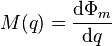
It can be inferred from this that memristance is simply charge-dependent resistance. If M(q(t)) is a constant, then we obtain Ohm's Law R(t) = V(t)/ I(t). If M(q(t)) is nontrivial, however, the equation is not equivalent because q(t) and M(q(t)) will vary with time. Solving for voltage as a function of time we obtain

This equation reveals that memristance defines a linear relationship between current and voltage, as long as charge does not vary. Of course, nonzero current implies time varying charge. Alternating current, however, may reveal the linear dependence in circuit operation by inducing a measurable voltage without net charge movement—as long as the maximum change in q does not cause much change in M.
Furthermore, the memristor is static if no current is applied. If I(t) = 0, we find V(t) = 0 and M(t) is constant. This is the essence of the memory effect.
The power consumption characteristic recalls that of a resistor, I2R.

As long as M(q(t)) varies little, such as under alternating current, the memristor will appear as a resistor. If M(q(t)) increases rapidly, however, current and power consumption will quickly stop.
In circuit theory, magnetic flux Φm typically relates to Faraday's law of induction, which states that the voltage in terms of electric field potential gained around a loop (electromotive force) equals the negative derivative of the flux through the loop:

This notion may be extended by analogy to a single passive device. If the circuit is composed of passive devices, then the total flux is equal to the sum of the flux components due to each device. For example, a simple wire loop with low resistance will have high flux linkage to an applied field as little flux is "induced" in the opposite direction. Voltage for passive devices is evaluated in terms of energy lost by a unit of charge:

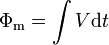
Observing that Φm is simply equal to the integral of the potential drop between two points, we find that it may readily be calculated, for example by an operational amplifier configured as an integrator.
Two unintuitive concepts are at play:
- Magnetic flux is generated by a resistance in opposition to an applied field or electromotive force. In the absence of resistance, flux due to constant EMF increases indefinitely. The opposing flux induced in a resistor must also increase indefinitely so their sum remains finite.
- Any appropriate response to applied voltage may be called "magnetic flux."
The upshot is that a passive element may relate some variable to flux without storing a magnetic field. Indeed, a memristor always appears instantaneously as a resistor. As shown above, assuming non-negative resistance, at any instant it is dissipating power from an applied EMF and thus has no outlet to dissipate a stored field into the circuit. This contrasts with an inductor, for which a magnetic field stores all energy originating in the potential across its terminals, later releasing it as an electromotive force within the circuit.
An applied constant voltage potential results in uniformly increasing Φm. Numerically, infinite memory resources, or an infinitely strong field, would be required to store a number which grows arbitrarily large. Three alternatives avoid this physical impossibility:
- M(q) approaches zero, such that Φm = ∫M(q)dq = ∫M(q(t))I dt remains bounded but continues changing at an ever-decreasing rate. Eventually, this would encounter some kind of quantization and non-ideal behavior.
- M(q) is cyclic, so that M(q) = M(q − Δq) for all q and some Δq, e.g. sin2(q/Q).
- The device enters hysteresis once a certain amount of charge has passed through, or otherwise ceases to act as a memristor.
The memristor was generalized to memristive systems in a 1976 paper by Leon Chua.[10] Whereas a memristor has mathematically scalar state, a system has vector state. The number of state variables is independent of, and usually greater than, the number of terminals.
In this paper, Chua applied this model to empirically observed phenomena, including the Hodgkin–Huxley model of the axon and a thermistor at constant ambient temperature. He also described memristive systems in terms of energy storage and easily observed electrical characteristics. These characteristics match resistive random-access memory and phase-change memory, relating the theory to active areas of research.
For some memristors, applied current or voltage will cause a great change in resistance. Such devices may be characterized as switches by investigating the time and energy that must be spent in order to achieve a desired change in resistance. Here we will assume that the applied voltage remains constant and solve for the energy dissipation during a single switching event. For a memristor to switch from Ron to Roff in time Ton to Toff, the charge must change by ΔQ = Qon−Qoff.

To arrive at the final expression, substitute V=I(q)M(q), and then ∫dq/V = ∆Q/V for constant V. This power characteristic differs fundamentally from that of a metal oxide semiconductor transistor, which is a capacitor-based device. Unlike the transistor, the final state of the memristor in terms of charge does not depend on bias voltage.
The type of memristor described by Williams ceases to be ideal after switching over its entire resistance range and enters hysteresis, also called the "hard-switching regime."[11] Another kind of switch would have a cyclic M(q) so that each off-on event would be followed by an on-off event under constant bias. Such a device would act as a memristor under all conditions, but would be less practical.